Sears Custom 10XL Project

<<< Previous Page

Next Page >>>

Page 8

       The original (broken) PAR-36 headlights were incandescent sealed-beam tractor lamps which draw more current than needed for the job. I opted to use some LED versions of the same lamp which can be ordered in a soft white (3000K) color temperature to mimic the vintage look of the old ones.

       The look of the new headlamps matches closely to what would have been shipped with the tractor new :0)

       So far so good.....

       The next step was to implement my starter control system which consisted of a battery voltage level switch, a timer circuit and a engine run sensor. The battery voltage switch will operate a light on the instrument panel when the battery is over 13.5 volts (indicating a charging state). The timer circuit will momentarily actuate the compression release (when starting) and the engine run sensor will lock out the actuator when the engine is running.
       All of these components were fitted into a waterproof housing as seen below...

       I 3D printed some standoffs which were screwed to the PCB boards and can easily be glued into the back of the enclosure as seen above/below.

       The trickiest part of getting this setup to work is figuring out how to tell if the engine is running without any power connected to the field winding of the starter generator. This is because the starter generator has no permanent magnets and uses a field winding to create a magnetic field for power generation in the armature (varied by the charge regulator). When the throttle lever is set below the 30% “start” setting the starter generator is not connected to the battery but the engine could still be running from a previous start cycle.
       I needed a way to detect if the engine is still spinning to lock out the function of the compression release actuator. For this circuit I used a signal amplifier board to detect very small voltages from the generator and boost them up to control an opto-isolated relay which in turn will lock out the actuator. The residual magnetism in the stator makes a detectable voltage on the output of the generator in the magnitude of .50 to .75 volts which triggers this circuit and prevents unwanted operation of the compression release actuator.
       The signal amplifier is barely visible on the left side of the enclosure below (yellow, orange and red wires are connected to it).

       I mounted the controller enclosure to the underside of the tractor and moved on to wiring the other components.

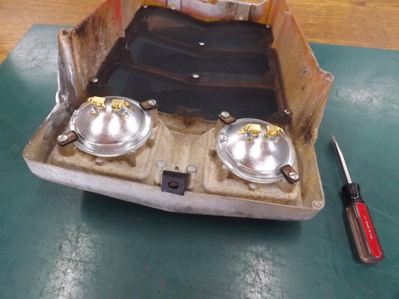
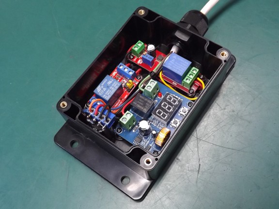
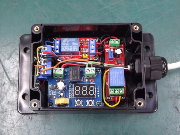
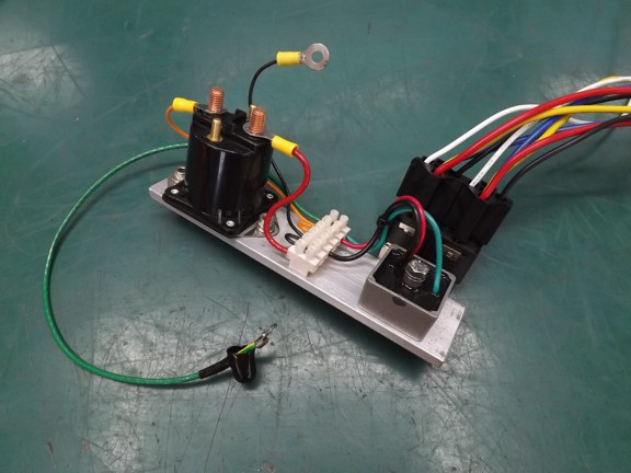
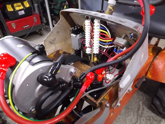
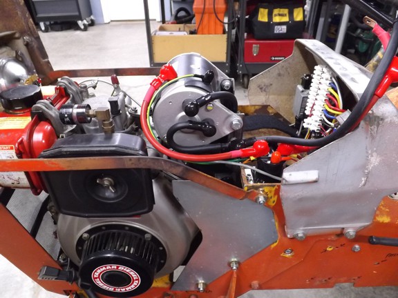
       The starter generator system works like a traditional starter except it is always spinning with the engine as where a traditional starter disengages from the engine. This allows the starter to feed back into the battery when the engine spins fast enough to reverse the current flow. Once the engine is spinning fast enough a charge regulator keeps the battery from overcharging by adjusting the field current. You can see the solid state regulator (bottom right) next to the power solenoid (left).
       The one thing to take note of is that if the engine is running too slow the starter will try and speed up the engine which will drain the battery instead of charge it. This is why you need to disconnect the starter generator at slow running speeds (30% in my case) to prevent this issue.

Note: The charge regulator seen below is a replacement for the original electromechanical regulator that I was going to use on this project. The solid state ones are super cheap and regulate far better than the old school ones...

       The use of terminal blocks really organizes a system like this and makes for great “testing points” for troubleshooting later...

       The high current wires that connect the battery to the starter generator require a good connection to reduce resistance. For this project I purchased a hydraulic press to install the terminal connectors to the ends of the wires which should reduce resistance in the circuit...

       The crimper makes a very professional looking termination :0)

       Most of the wiring was complete at this point and I was ready to test the functions of my new controller circuit...

       This style of golf cart starter generator can be wired up to run both clockwise and counterclockwise for use in dual direction 2-stroke engines (for a reverse function on some golf carts). This is done by reversing the connections on the back of the starter. We won’t be needing this function on this build...

       And now for the battery...

       The moment of truth has arrived!!! I could now test the starter generator.

       I turned the key switch on and tested the lights to make sure that system worked and then moved on to the start sequence. I pressed the clutch/brake pedal and rolled up the throttle to hear the diesel come to life. I was super impressed how smooth the starter spun up the engine for a quick start :0)

       The function of the start controller works as follows: First the key switch is turned to “run”. Next the clutch/brake pedal must be pressed down to close the start interlock switch (This prevents a start while in gear). Then the throttle is pushed up above 30% to start the engine with the starter generator. Simultaneously the compression release actuator holds the exhaust valve open for two seconds allowing the engine to spin up to starting speed without compression.
       Once the actuator closes the exhaust valve the engine starts and if the throttle is set high enough the system will charge the battery which is indicated by the charge light on the instrument panel. If the throttle is set below the 30% setting the starter generator is disconnected from the battery and will allow the engine to idle unassisted by the starter. If the throttle is raised again while it’s running the actuator lockout circuit will keep it from opening the exhaust valve again until the engine has stopped completely.

       I couldn’t help myself from driving the tractor at this point. The sound of the diesel engine really makes this project very satisfying ;0)

Tractor demonstration video coming soon!!!

       Now that most everything has been sorted out and functional I must start tearing it all apart for paint :0P

       I really wanted to play longer with the tractor but I knew I had a monumental task to complete and I needed to get started :0/

       I basically had to take every nut and bolt apart to start the painting process and keep track of everything for reassembly later on...

       Most of the metal parts will need to be sandblasted to remove 50+ years of rust and old paint.

       The tractor was originally a yellow color but had been repainted orange at some point by a previous owner. I wanted to get down to bare metal to ensure my new paint would stick.

       The transmission had already been painted so I just set it aside for later...

       I started sandblasting the parts in a makeshift enclosure in front of my shooting range as seen below. I used regular “playground sand” in my sandblaster which is not recommended these days due to risk of silica exposure to the lungs (causing a lung disease called silicosis). I was sure to use a respirator during the entire process virtually eliminating the risk of exposure...

       It took nearly 400 pounds of sand to clean off the yellow powder coating from the chassis and about 12 hours of work!!!

       The newly sandblasted surface of the parts will adhere to the primer very well :0)

       The “hood” had some rust pitting which was filled with body filler (Bondo)...

       I then used some high-fill primer to smooth out the imperfections along with lots of wet sanding. I also filled in the rust pitting in the fenders at this time (not shown) with the same process...

       Next I used an automotive primer to coat all of the bare parts and set them out in the sun to dry.

       I lightly sanded all of the primered parts to knock down any high spots in preparation for final paint (not shown).

<<< Previous Page

Next Page >>>

[Home] [What's New At RCDON] [Articles] [Aircraft Projects] [Aircraft Videos] [Aircraft Videos II] [Experimental Projects] [Experimental Projects II] [Nixie Tube Clock Project] [6CI Steam Engine Project] [Vertical Boiler Project] [The Toolroom Tune-Up Project] [The Reverse Tumbler Project] [Red Wing Engine Project] [MakerGear M2 Project] [The LED Studio Light Project] [Sears Custom 10XL Project] [My Collection] [RC Links] [About Myself] [Contact RCDON]