|
|
|
|
|
|
|
|
|
|
|
|
|
Posted on October 22, 2007
Every now and then I discover something on the internet that captivates my imagination and fires up my creativity. Most of the time I cant help myself from wanting to know more about the discovery and sometimes I end up with a whole new hobby :0P Well Nixie tubes have proven to be another one of those discoveries and so far I am hooked.
A Nixie tube is a generalized term for a cold-cathode neon indicator tube which was popularized by the Burroughs Corporation in 1956. It is a common belief that the term NIXIE was derived from Burroughs term Numeric Indicator eXperimental No.1 or NIX1. Later other companies would call the indicator tubes Numicators or Digitrons but for the most part would always be known as the Nixie Tube.
Nixie tube displays were used on equipment that needed a digital readout like calculators, frequency counters and early computers. This was long before LCD (Liquid Crystal Display) and LED (Light Emitting Diode) displays were available for use. Several variations of the Nixie were developed all having the display elements encased in a glass envelope. Incandescent filament readouts or Numitrons as well as Vacuum Florescent Displays or VFDs were other popular display tubes but only the Nixie used a neon gas to illuminate a cold-cathode element.
A Nixie tube is comprised of glass tube envelope containing several alphanumerical display cathodes stacked on each other (usually numerals 0-9) but electrically insulated from one another. A screen mesh anode surrounds the cathodes but allows the viewing of the front of the cathode indicators. A low pressure neon gas is used inside the glass envelope and is illuminated when DC current flows through any one of the cathode indicators. The voltage used to excite the neon gas is around 140-180 volts DC at anywhere from .5 to 25 ma (depending on the size of the tube). This current produces a very warm glow of neon gas that surrounds the cathode and creates that very desirable Nixie tube look.
Several factors predict the life of a Nixie tube including burn time, cathode current, the tubes hermetic seal integrity and something called cathode poisoning. Cathode poisoning is where unused cathodes accumulate sputtering from other working cathodes preventing them from illuminating. This sputter is material emitted from the working cathodes and can deposit on other cathodes or just deposit on the glass itself making the display unreadable. Typically healthy Nixie tubes can have a working life anywhere from 5,000 to 200,000 hours, depending on what technology was used to manufacture them.
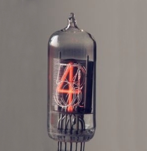
Below are a couple of examples of Nixie tubes. On the left is a Telefunken ZM 1210 tube which is about 1.9 tall and on the right are the highly prized and rare Okaya Rodan CD 47/GR 414 Nixie tubes which stand 8.7 tall !!!
|
|
|
 |
|
 |
|
|
Nixie tubes for the most part had began their decline in the 1970s with the advent of newer technologies. Ultimately the Nixie tube would be replaced by LED, LCD, VFD and CRT (Cathode Ray Tube) displays. By 1990 almost all of the Nixie manufacturers stopped producing the displays ending the tubes 40 year career. This did not mean the end of our friend Mr. Nixie oh no. In fact the Nixie tube has become one of the most collectable display devices ever made. Little did I know that since the late 80s these tubes have gained notoriety and have been highly sought after by the tube collector. Some of these Nixie tubes are being used in home-brew digital clocks giving them a new purpose in life.
I discovered the Nixie craze on eBay when I was looking for a vacuum tube Thyratron and stumbled on the other tubes category. I could not belief the activity going on with all kinds of projects and uses for the old Nixie tubes. I vaguely remembered the tubes in old equipment I took apart as a curious child but that was 25 years ago. I had no idea that there were so many varieties of tubes or how widespread their use was back in the day.
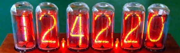
Being captivated by the hypnotizing glow of the Nixie I purchased a clock kit from a supplier in Hong Kong through eBay (NixieTimeSolutions.com). The clock kit utilizes six Russian made IN-16 Nixie tubes which were new surplus tubes made in the 80s. I received the kit and completed it within a few hours of getting it. In all honesty I fell in love and could not stop watching the tubes warm glow. Here are a few pictures of my first clock project that I built in early September of this year.
|
|
|
 |
|
|
|
 |
|
|
|
 |
|
|
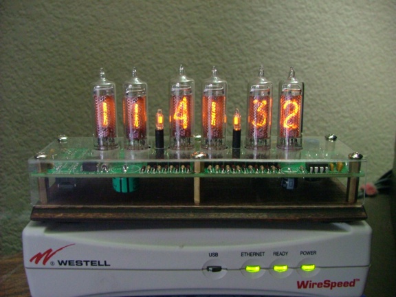
It wasnt long before I was looking on eBay for other Nixie tubes to collect and new clock kits to build. Within a week I had won another auction for a kit that uses the famous Russian IN-18 Nixie tubes. The V1.08 clock kit I won is made by www.NixieClocks.de in Germany and is a fine piece of electronic craftsmanship. I received the kit from Germany as well as the IN-18 Nixie tubes I purchased from an eBay seller in the Ukraine. The only additional part I needed to come up with was a 12 volt AC power adaptor (which I found on eBay as well).
|
|
|
 |
|
|
The NixieClocks.de kit uses a multiplexed tube decoder/driver circuit that handles three tubes on one decoder IC for a total of two ICs for six tubes. This means that a multiplexed signal (a signal with more than one set of instructions) is transmitted to three tubes simultaneously and each tube receives its own set of instructions via a phase shifted anode voltage gate signal. This gate signal is in phase with the corresponding tube decoder signal so if you wanted the number 3 to light up on the second tube you would send a 3 signal on the second anode gate phase voltage. Sound simple enough? Well, I am no expert on this stuff so maybe I will leave it to the educated ones ;0) To learn more about multiplexing you can check out this site:
Onnos Electronics Page - How to drive Nixie tubes
I really liked this kit in particular because it can use your household AC power frequency (60 Hz) to regulate the clocks speed. The frequency of household AC power is tightly regulated to 60 Hz which allows you to use it to tell time. The Nixie clock kit uses a counter circuit to measure the cycles per second of the 12 volt AC power (supplied by a transformer adaptor) to tell the time accurately without a satellite signal. The kit will also tell time with an internal frequency generator but it is not needed unless you plan to run the clock on 12 volts DC.
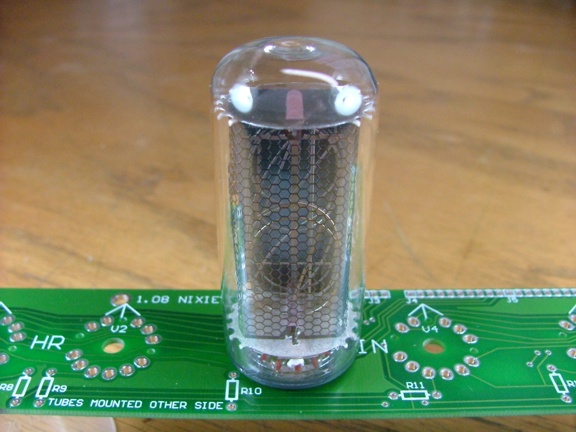
The whole basis and point of this clock is to use the beautiful IN-18 Nixie tube. The IN-18 was made in Russia by the Reflector/Sovtec plant. They were manufactured from 1970 to as late as 1991 and produce a beautiful Arabic numeral when lit. The tubes are 86 mm high and 32 mm in diameter. The numeric symbols of the IN-18 are 40 mm high which when compared to the IN-16 tube (my first clock) are 27 mm taller !!!
|
|
|
 |
|
|
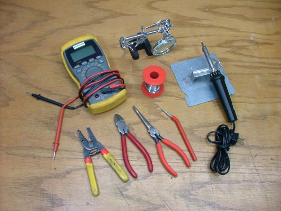
To build the kit I just needed a few tools including my digital multimeter, soldering iron and wire cutters etc..
|
|
|
 |
|
|
|
The kit included all of the electronic parts needed to make the basic clock less the IN-18 tubes and power supply. As you can see there isnt much too it. Thats because the real clock is in the PIC (Programmable Intelligent Computer) chip which saves a bunch of space. The multiplexed tube driver circuit also saves a lot of space by eliminating a lot of components.
|
|
|
 |
|
|
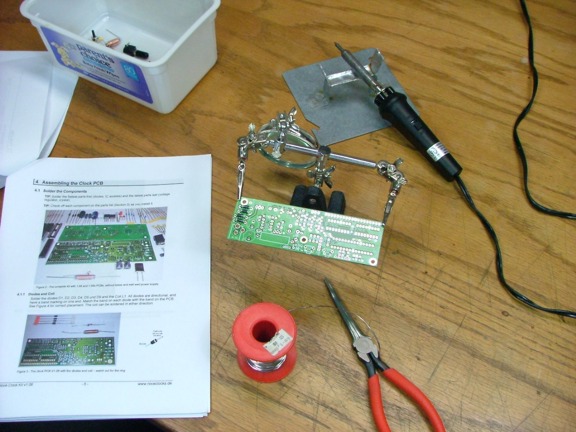
Before I soldered anything together I read the instruction booklet thoroughly. I then checked to make sure that all of the parts on the parts list were accounted for, checking them off the list as I went. Notice my Radio Shack resistor color code chart that I used to identify the resistors (below).
|
|
|
 |
|
|
|
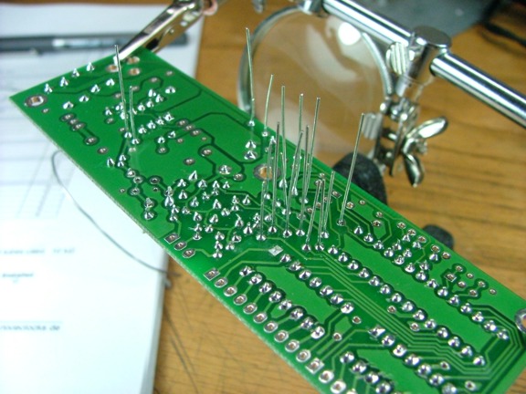
To help hold the printed circuit board I used my helping hands device as seen below. This is an inexpensive and useful tool for electronics projects.
|
|
|
 |
|
|
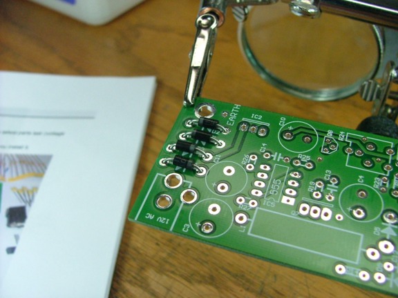
I started out by installing all of the flat or low profile components first as to eliminate obstructions later on due to taller components blocking your workspace.
|
|
|
 |
|
|
 |
|
|
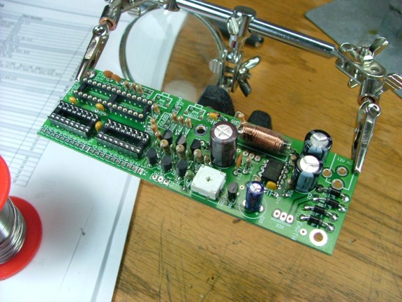
The kit uses several high voltage transistors to sequence the multiplexed anode gate voltage via the PIC processor. The high voltage itself is generated by a DC to DC converter on the board.
|
|
|
 |
|
|
|
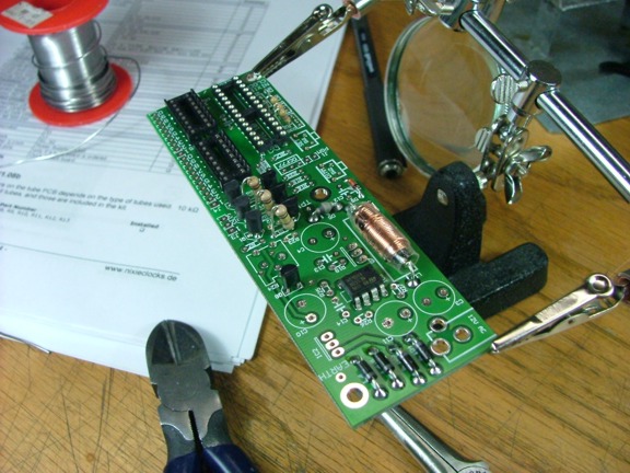
I usually like to solder the components in with the lead wires at full length. Once soldered I cut them flush with the diagonal cutters.
|
|
|
 |
|
|
 |
|
|
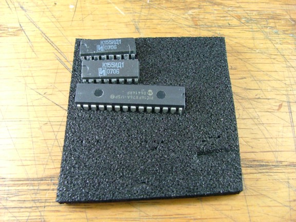
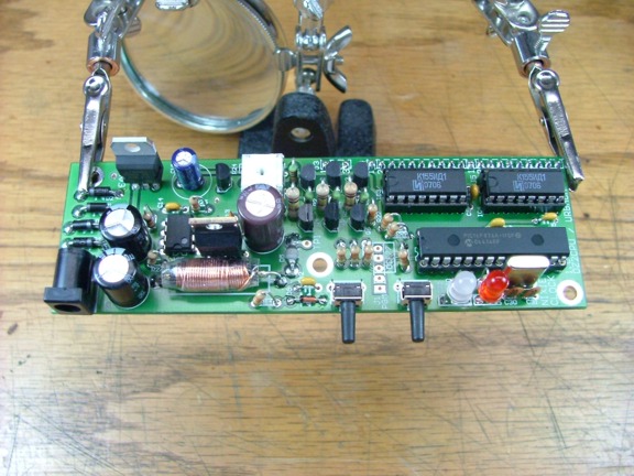
The mainboard of the kit went together very quickly and was ready for the installation of the Russian K155ID1 decoder ICs (SN74141) and the PIC processor. Notice the antistatic foam the chips are shipped in. They can be damaged by static electrical charges easily so you have to be careful.
|
|
|
 |
|
|
|
 |
|
|
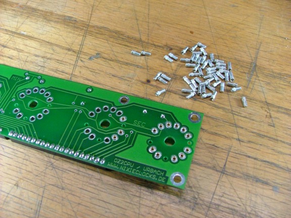
The clock electronics were basically complete now. I just needed to complete the tube board and connect it to the clock board via a multi-connector. To prepare the tube board for the Nixie tubes I installed a set of Mouser Pins (66 total) which are pin receptacles used for the IN-18 tube pins. I had ordered these as an optional item for the kit. Otherwise I guess you would be soldering in your very expensive IN-18 tubes...... NOT!!!!
|
|
|
 |
|
|
Next Page >>>
|
|