 |
|
|
|
|
Posted on July 19, 2020:
Hello again folks, its been quite a long time since I have written anything for the site (more than 5 years to be exact!!!) and its quite depressing :0( Things in my life have made it difficult to spend the quality time it takes to write updates and it has taken a toll on my creative momentum. I have been dormant so long that it is difficult for me to corral my thoughts together long enough to make a coherent article! Tough as it may be Im going to give it a shot.
Note from the author:
A lot has developed in the last six years within the world of information technology, specifically social media and the likes (no pun intended). Almost anyone can showcase their talents on the web (with great reward for some). This trend has brought forth a culture of makers that had it not been for these media platforms may have never discovered their talents. Either way there is no disputing that people are learning from the web exponentially and the future is just getting smarter.
I am personally astonished at the amount of absolutely brilliant people sharing their projects on the web now. It makes my contributions seem insignificant however I know that it is important to not think that way. One might become extremely discouraged instead of being inspired just by comparing one self to another. Every one of us is unique and has something worth sharing and it is up to us to express ourselves or stay dormant.
I know that my projects may not be as amazing as what others may have forged but that shouldnt discredit my contribution no matter how great or small. As long as there is someone out there that finds my work informative it is worth my time to write. For that I will continue to create and be part of the technology community as a productive member. Thanks for reading this article and thanks for supporting creative thought by sharing your own projects as well!
OK, now back to the matter at hand!
This is an article that I was planning to write back in January of 2016. Although the content may be dated, the project itself was a lot of fun to create. My hopes are that I can capture the mood of the project and share the sense of discovery I had during the build. Whether the project is currently relevant is up to your discretion however I do appreciate your consideration so here goes!!!
Amazing breakthroughs in LED (Light Emitting Diode) technology are continually being developed and back in 2015 some big ones were becoming available to the consumer market. The emerging technology of high powered COB (Chips On Board) LEDs were being developed in anticipation for commercial-industrial and consumer use in modern luminaries (light fixtures). At the time there was sill a need for cost effective area lighting as a majority of commercial industry still relied heavily on conventional lighting for factories and warehouses.
At the time of this article I was fascinated with the new COB LED packages that were being introduced from China, South Korea and Taiwan. These new LEDs were compact, powerful and best of all, cheap! I had to experiment with some of these new components so I ordered a few 50 watt chips and got to tinkering!!!
|
|
|
 |
|
|
My quest started out as a simple task: to create a super bright security light for my home. At the time the only type of LED security lights offered for consumer use were at most 30 watts in power (equal to the same light of a 150 watt incandescent lamp) which didnt have much punch compared to the old 300 watt quartz-halogen unit had. I was super disappointed that nobody had brought an industrial-grade solution to market as a gold standard for residential security lighting. I know that statement might sound funny but I wanted the very best and so I had to make my own.
Over the years I have had a few incidents of theft from my driveway. From what I learned from my security cameras I can tell that the thiefs didnt pay any attention to the security lights I had. In fact, I believe they appreciated the light so they could see what they were stealing from my work truck!!! This really bugged me as I thought the halogen lights I had were bright enough to scare away any would-be robber.
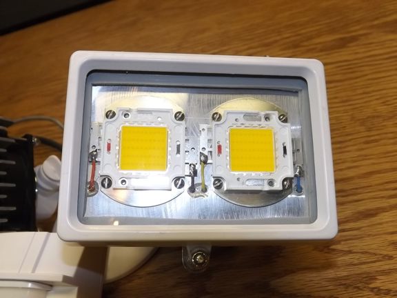
To fix this problem I decided to create a compact powerhouse of a security light that would blow the doors off of anything commercially available. To do this I employed four x 50 watt COB LED modules (seen below) of which use the COB architecture to encompass 50 x 1-watt LEDs on one substrate/heat sink. The 50 watt LED array is able to produce about 4500 lumens where as the same wattage quartz-Halogen source would produce about 900 lumens.
Note: A lumen is the measurement of a total quantity of visible light emitted by a source per unit of time. This measurement has widely been adopted as the expression of light produced by a source and a means of rating LED performance. A 100 watt Tungsten incandescent lamp produces about 1600 lumens which is the same light produced by a 18 watt LED lamp.
At the time I had a 300 watt Halogen motion triggered security light that was always being activated by the neighbors. Not only was the light fairly weak, it was expensive to run. I decided to use the parts from the old halogen light to make a new high-horsepower model as seen below. I incorporated 4 x 50 watt warm white 3500K chips into this new light which would produce about 18,000 lumens compared to the existing 5400.
|
|
|
 |
|
|
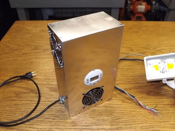
I mounted two chips on their own dedicated heat sink (one for each side) with an 80mm cooling fan mounted to the back (not shown). This new LED version came out to about the same size as the Halogen housing I replaced it with (not shown). Each chip is powered individually with its own constant current regulator which must be housed in a remote power supply enclosure (seen below).
|
|
|
 |
|
|
The remote enclosure has a 350 watt 24 volt DC power supply that powers up the four constant-current LED diver boards when the light is activated by the motion sensor. A special timer module was used to disable two of the four chips during the first few hours of night so as to not disturb the neighbors (more than I already do). After 11:00 PM the lights go to 100% brightness giving the full shock-and-awe effect!!!
The enclosure was mounted on the inside of the garage near the lights (not shown).
|
|
|
 |
|
|
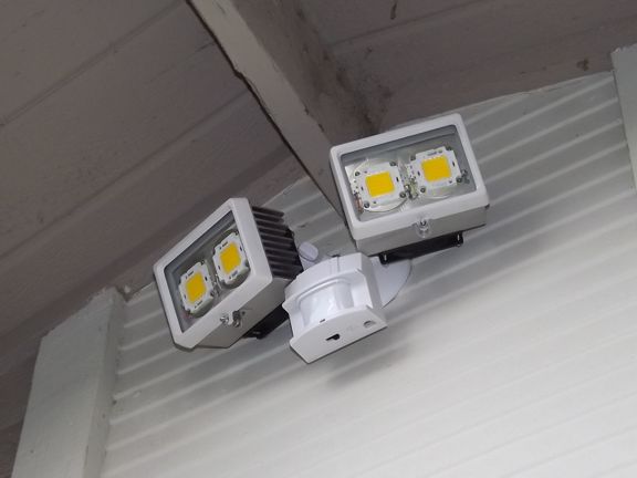
The over all look of the mounted security light was about as obtrusive as the original (not shown) which was a must considering it is right over the garage for everyone to see :oP
|
|
|
 |
|
|
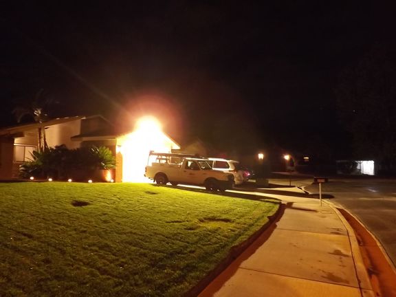
And now the moment of truth, would it be bright enough to send the prowlers running? Heck yes it was!!! Absolutely night and day as it were. There was no comparison to the old light and bright enough to bring a lot of attention to what is going on in my driveway. The best part of the new light is that it draws 25% less power than the original halogen system did.
Since these lights were put up in 2015 there have been no issues with theft from my work truck and in 2020 they are still the brightest security lights in the neighborhood ;0)
|
|
|
 |
|
|
With the success of the garage light project I began to ponder what else could be done with the new LED chips. There had never been a time before where one had the ability to experiment with high power modules such as these at such a reasonable price of $6 a piece. The horsepower-to-weight factor was also intriguing as you could gang multiple chips to create a photon cannon if you wanted ;0)
After thinking about it for a while I decided to see if I could create an LED powered studio floodlight that I could use in my film making hobbies. A light that would be as compact as I could make it and yet have an obscene amount of power to illuminate large areas with ease. All of this and be able to power it with a standard 110 volt 20 amp household circuit.
At the time of this project there wasnt anything like it so the design had to be from the ground up. As with most of my projects I started out by daydreaming different designs in my mind. I would build different configurations virtually till I could see the design working in my head which is something I have done since I was a kid.
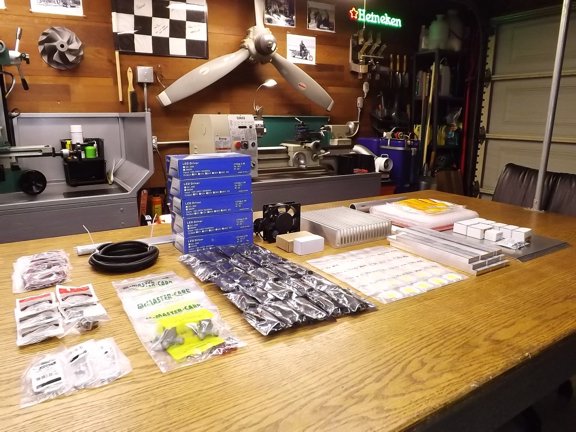
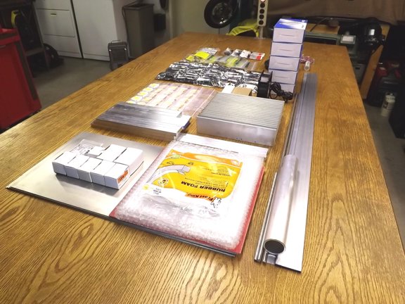
Once I settled on a design plan I started collecting all of the parts to make the super lumenator.
|
|
|
 |
|
|
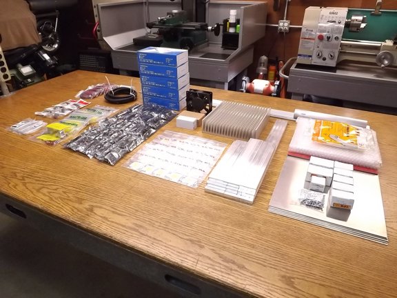
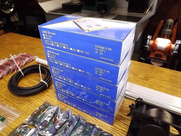
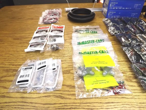
I sourced most of my material from eBay and Amazon which took about a week and a half. This included the COB chips, drivers, power supplies, aluminum (for the chassis), cooling fans, wiring and the all important heat sink.
|
|
|
 |
|
|
My light design is mostly based on wattage as I wanted the most powerful light that can be plugged into a standard household outlet. The max power that can be safely pulled from 20 amp 120 volt household circuit is about 2000 watts (16.6 amps @ 120 volts). Using this power envelope as a limit I chose to use 25 x 50 watt chips which when including efficiency losses would come out to be about 1800 watts.
I chose to use the 50 watt chips over a 70 or 100 watt design as they have a good diode to surface area ratio making them easier to cool. This will be especially important as all 25 chips will be on the same heat sink. If all goes well the array of chips should produce over 112,000 lumens!!!
|
|
|
 |
|
|
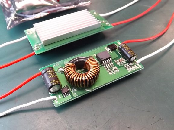
The COB chips will be driven by independent purpose built driver boards (seen below) which will provide constant current to drive the diodes.
|
|
|
 |
|
|
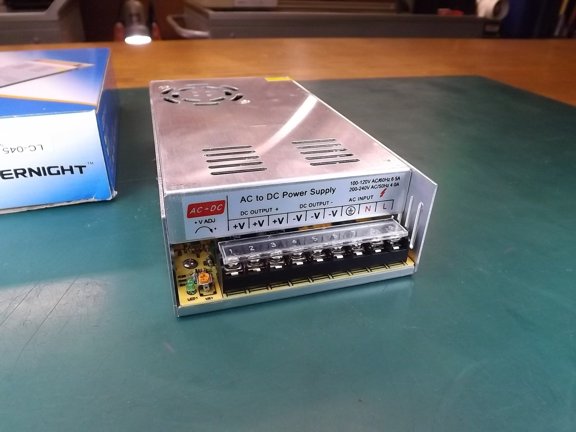
I will be using five AC to DC power supplies to power the drivers which are going to take up most of the real-estate inside of the light head.
|
|
|
 |
|
|
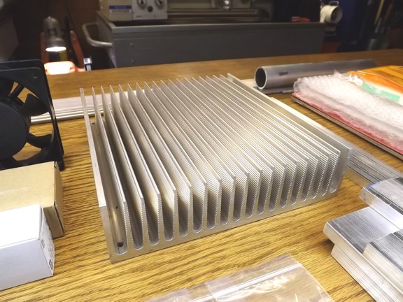
LEDs are way more efficient than Tungsten lamps however they still arent perfectly efficient. At the time of this build the chips being used were about 38% efficient meaning that 62% of the power used by them turns into heat. That would mean that if all of the chips are running at the same time they will produce 775 watts of heat!!! Thats 2,600 BTUs per hour that will need to be expelled by the heat sink.
Finding such a heat sink was not easy believe it or not. Commercially available (new) heat sinks in this size were several hundred dollars but I was lucky to find a used one on eBay for around $42 shipped. Along with a 120 volt cooling fan this 8.4 pound heat sink will have to keep all of the chips running at under 70° C or else my light will go up in smoke!
|
|
|
 |
|
|
Finding parts for a project can be a lot of fun. I love the challenge of finding all of the parts I will need at the beginning of a project as opposed to buying stuff as the project progresses. Note: This rarely works perfectly as plans usually change along the way so use this ideology with caution.
|
|
|
 |
|
|
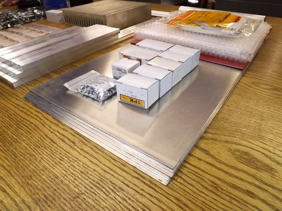
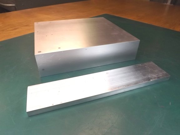
I purchased a lot of aluminum sheeting that will be used for the body of the light head. This 5052 aluminum sheeting (.063) along with 6061 bar stock will make up the light head chassis.
|
|
|
 |
|
|
 |
|
|
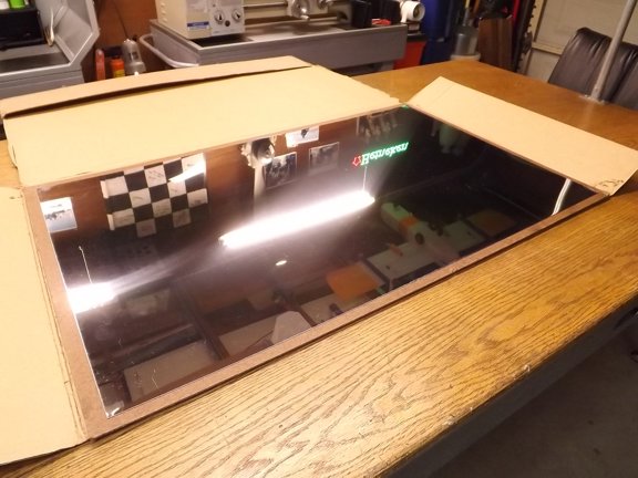
I also bought a sheet of highly polished 22 gauge 430 stainless steel which will be used as a reflector later on.
|
|
|
 |
|
|
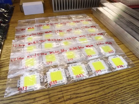
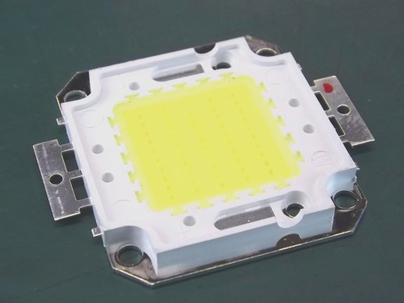
The star of the show are these COB LED 50 watt chips as seen below. These chips or modules have 50 x 1 watt LEDs mounted onto a single copper base plate which will transfer the heat from the diodes into a heat sink of which they will be mounted to. The chips require 32 to 36 volts at 1.5 amps to run at full power and produce light in the 6500K color temperature (bright white light).
The color temperature (expressed in Kelvin) is important in film making so I chose to use a temperature that would lend itself as overcast daylight or moonlight for a dramatic effect. Color correction filters can also be used to soften up temperature if needed.
|
|
|
 |
|
|
You can barely see the five rows of LEDs (10 each) which are connected in series of which are then connected in parallel to the two tabs seen on each side of the chip. Each individual diode on the board takes about 3.3 volts at 30 milliamps to run which equates to 1 watt of power in.
|
|
|
 |
|
|
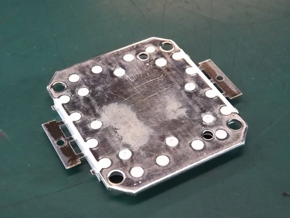
LED lamps are much more efficient than incandescent lamps but still produce heat as a byproduct. The nickel plated copper base seen below is used to transfer that waste heat to a heat sink for removal.
|
|
|
 |
|
|
To make to most compact and portable light head I needed to arrange the chips in a pattern that would fit onto a single common heat sink. The 5 x 5 pattern seen below is what I settled on providing the right amount of heat sink area to each module.
|
|
|
 |
|
|
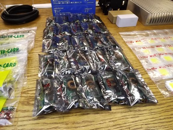
To efficiently power each LED chip I will be using a purpose built LED driver board as seen below. These boards take 12 to 24 volts and boost it to 32 to 36 volts at a constant 1.5 amps. This constant current ensures that the LED chip is not overdriven and provides the best longevity for the chip.
|
|
|
 |
|
|
I will be using 25 of the driver boards so each of the chips will have independent regulation. This will also allow the LED array to be switched on in sections or banks to produce the exact light needed.
|
|
|
 |
|
|
The DC power that runs the driver boards will come from five 350 watt AC to DC power supplies that produce 24 volts DC at 14.6 amps. This is enough to power five driver boards which require about 2.3 amps each at 24 volts.
|
|
|
 |
|
|
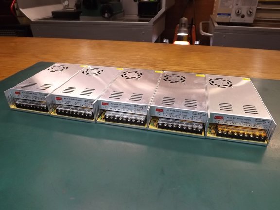
The five power supplies (seen below) will have to fit into the light head which will be a challenge.
|
|
|
 |
|
|
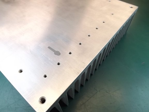
To start off my project I decided to build the light head frame around the power supplies so that the exact fit of all of the parts can be done before working on the LED array. This will all start with the heat sink seen below.
|
|
|
 |
|
|
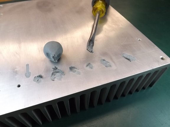
This heat sink spent its previous life in a high power amplifier so there are a few existing holes on the face. To help keep cooling air from passing through the heat sink I decided I must seal the holes as they will not be used.
|
|
|
 |
|
|
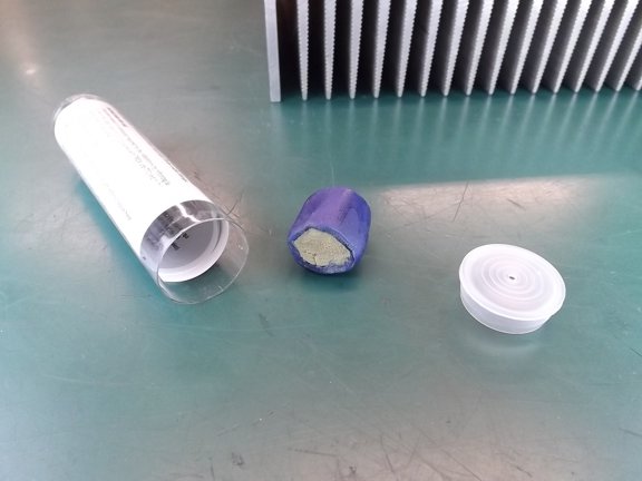
I used an electrical grade epoxy sealant to fill the holes. This is the kind you just have to knead before using.
|
|
|
 |
|
|
The Crouse-Hinds TSC two-part epoxy was easy to use and is designed to stick really well to aluminum.
|
|
|
 |
|
|
 |
|
|
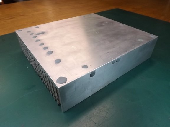
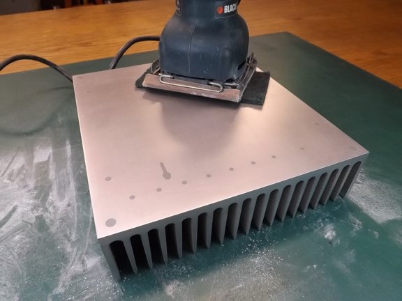
Once the epoxy had cured I sanded it down flush...
|
|
|
 |
|
|
The next step was to add a header block to both sides of the heat sink to make up for the fact the heat sink is not square.
|
|
|
 |
|
|
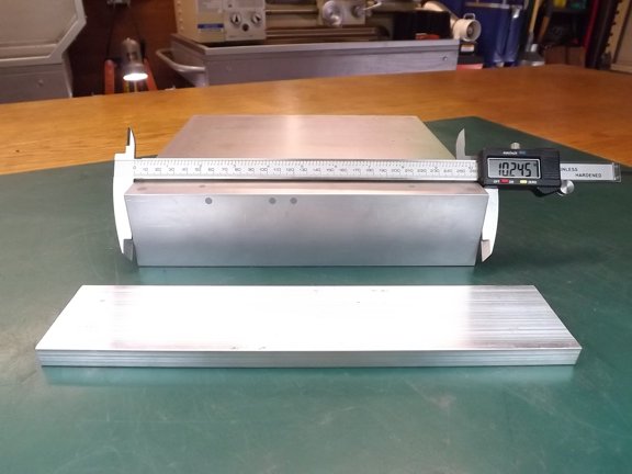
The heat sink has a dimension of 10.245 x 9.267 which means that it is rectangular. I wanted to add a set of headers to the long sides of the heat sink to make more of a square footprint for the LED chips to mount to. To do this I needed to prepare two 1/2 x 2-1/2 6061 aluminum bars.
|
|
|
 |
|
|
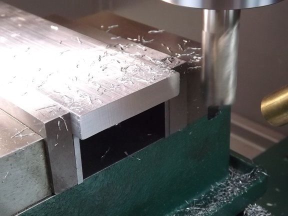
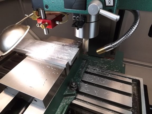
I needed cut the bars to the right length so I squared up my mill vise to face precision ends on the bar stock. If the vise is not square with the table travel the ends of the bars will be angled.
|
|
|
 |
|
|
The mill can provide a very precision surface angle to the ends of the bars so the frame will remain square.
|
|
|
 |
|
|
Both top and bottom header bars were squared on the one end.
|
|
|
 |
|
|
Next Page >>>
|
|

