The LED Studio Light Project

<<< Previous Page

Next Page >>>

Page 2

       The next step I performed was to cut the header pieces to the exact length needed which was about 9.245” long. I used Dykem machinists layout fluid to easily see the scribe marks on the bar stock. Using my band saw I cut the bars just a bit longer than needed.

       A quick splash of Dykem on the end will make it easier to see where I have milled.

       And now for a quick pass with the 3/4” HSS end mill. I milled up to the scribed line on the Dykem and then zeroed in the exact length by checking it with calipers (not shown).

       I am now finished with the two header bars. I also made two tail end frame supports that are the exact same length but only 1” wide as seen below.

       The next step was to cut all four frame rails that will run along the length of the light head. These will be made out of 1/2” x 1/2” 6061 bar stock and cut to a length of 15.5”.

       The same method was used as before except all four rods were cut at once.

       The next step was to drill holes to mount the rails to the header blocks. This was initially done with a #25 AWG drill so the rail could be used as a drill guide for the 10-24 tapped hole in the header blocks.

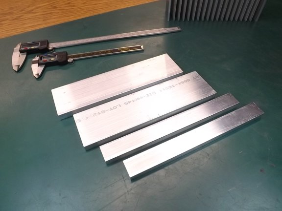
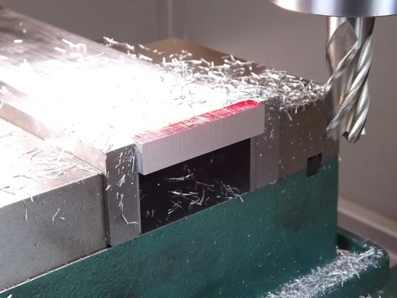
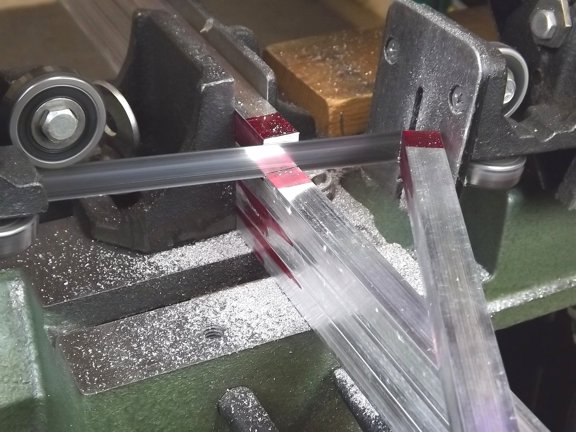
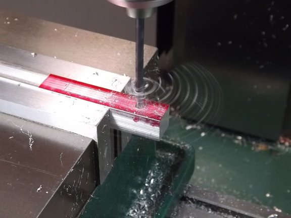
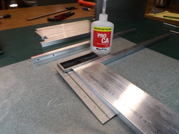
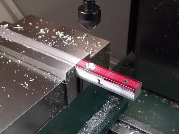
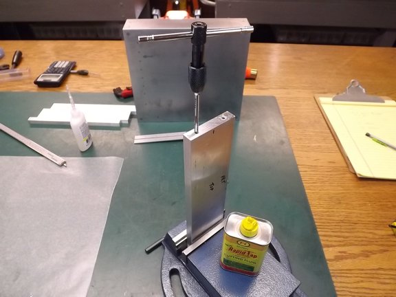
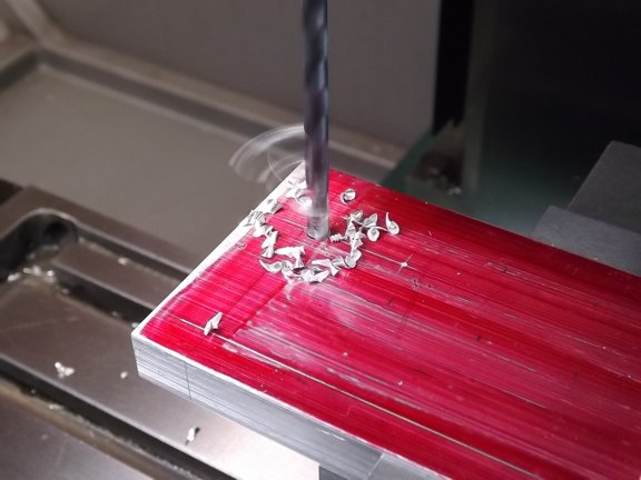
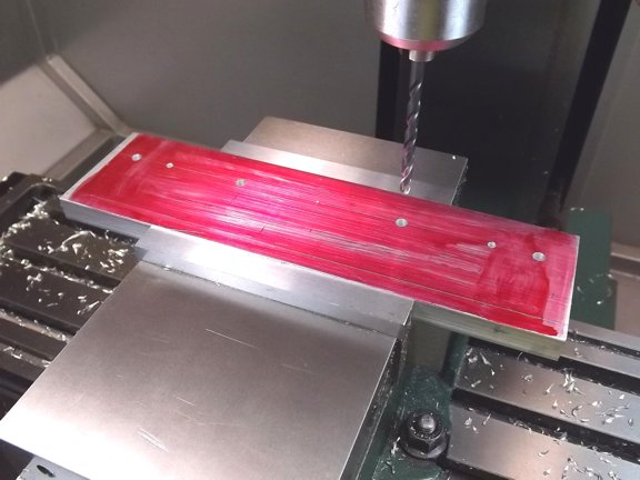
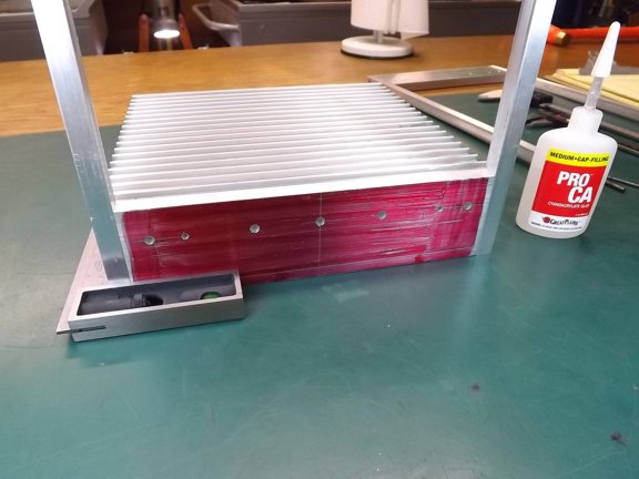
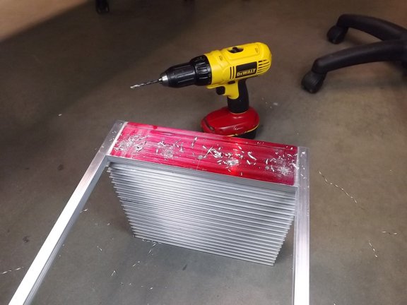
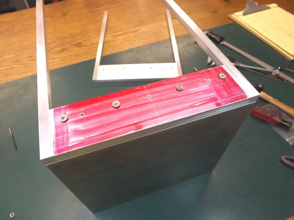
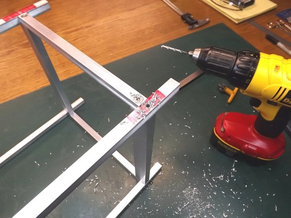
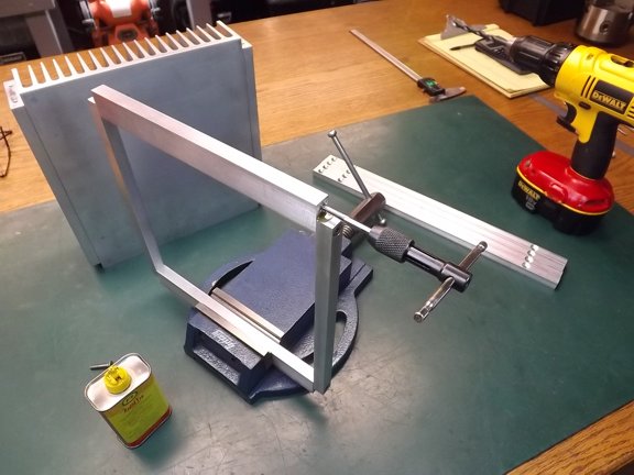
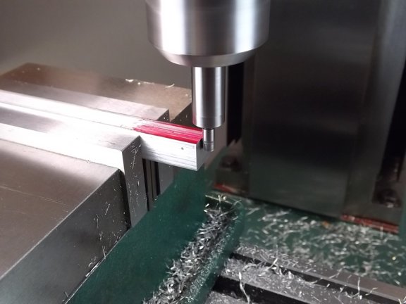
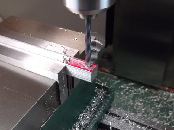
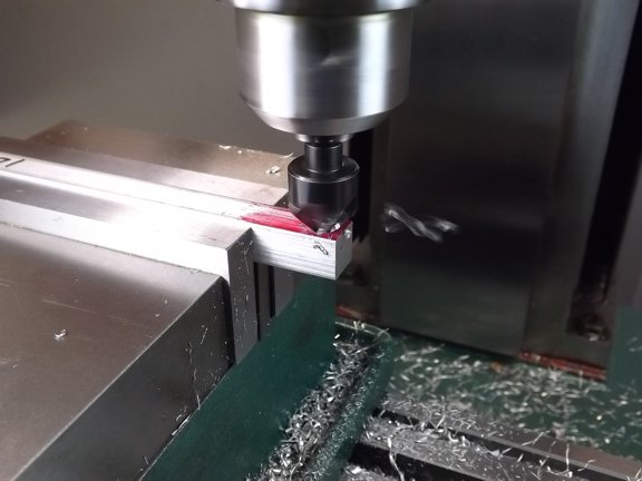
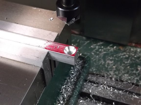
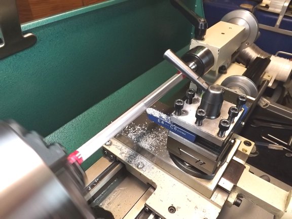
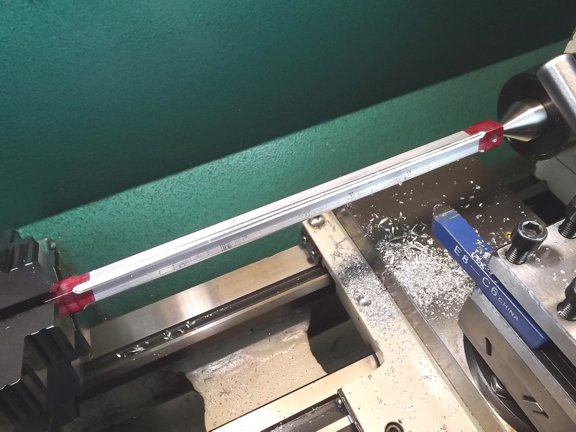
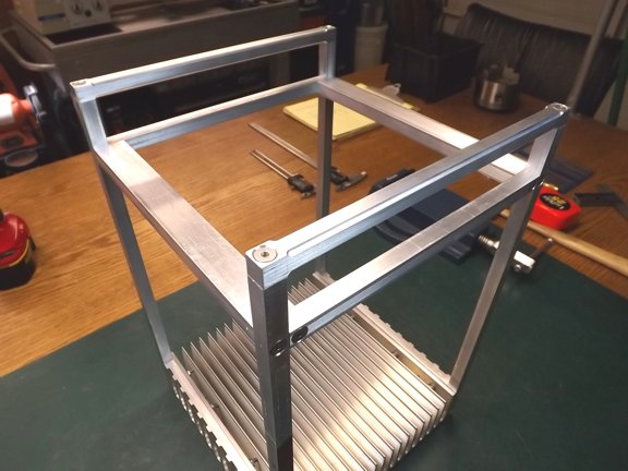
       To make sure the holes line up I glued the block to the rails with a bit of CA glue (Cyanoacrylate). This stuff is great to help layout parts as it can easily be released with a bit of heat from a torch. You can then dissolve the CA residue with a bit acetone but don’t get it near any open flames of course.

       With the rails glued into place I used the #25 holes in the rails as guides to drill for the tapped holes in the header blocks.

       After removing the rails from the blocks I widened out the holes in the rails to a #11 drill size to allow the threads of the 10-24 screws to fit (not shown). I then used a 90° countersink bit to allow the flathead hardware to be flush with the surface.
Note: Every part was numbered and identified for orientation so as everything would fit correctly during final installation.

       And now for the 10-24 tap. A few drops of Rapid Tap fluid goes a long way providing a clean thread and long tool life.

       I used 10-24 x 1” 18-8 stainless screws to attach the aluminum pieces which worked really well. A solid choice for 6061 of these dimensions.

       The next step was to attach the header blocks to the heat sink. This would be done with four 10-24 screws and a set of roll pins. The four #11 holes were drilled into each header block along with two #30 holes for my 1/8” roll pins.

       I glued the block to the heat sink and first drilled the #30 holes to set up the roll pins which will keep the headers from shifting later on.

       The roll pins were driven into the header blocks...

       You can see where the roll pins will meet the heat sink below.

       I joined the two together and drilled with the #11 bit for the screws.

       A quick test of the hardware...

       The next step was to mill out some cooling channels into the header blocks for additional cooling. This was done with a 1/2” HSS end mill as seen below.

       Once the channels were finished I countersunk the screw holes.

       The mounted blocks really came out nice ;0)

       The next step was to cut a couple of cross rails at 9.267” long to attach to the previously made 1/2” x 1” tail end support braces. These rails were drilled and tapped as described before and fitted to the braces for attachment to the side rails.

       The tail end frame assembly was positioned so that it was 1-1/2” in from the end of the side rails. It was there that they were attached to the side rails as seen below.

       The next step was to drill and tap the ends of the side rails for handles. This was done by first centering the rails in a four-jaw chuck using a dial indicator.

       A #25 hole was drilled on the tail end of each side rail now.

       Two handles were cut at 10.267 long and set into the mill for holes on each end. An edge finder was use to precisely locate the #11 hole in the handle at 1/4” in from the end.

       The handles needed to be rounded a bit so there were no sharp edges. This was done with a 1/4-round lathe bit to a diameter of 0.60”.

       The handles were mounted for a test fit. Looking good so far...

<<< Previous Page

Next Page >>>

[Home] [What's New At RCDON] [Articles] [Aircraft Projects] [Aircraft Videos] [Aircraft Videos II] [Experimental Projects] [Experimental Projects II] [Nixie Tube Clock Project] [6CI Steam Engine Project] [Vertical Boiler Project] [The Toolroom Tune-Up Project] [The Reverse Tumbler Project] [Red Wing Engine Project] [MakerGear M2 Project] [The LED Studio Light Project] [My Collection] [RC Links] [About Myself] [Contact RCDON]