The LED Studio Light Project

<<< Previous Page

Next Page >>>

Page 3

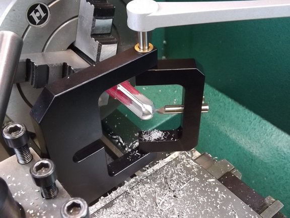
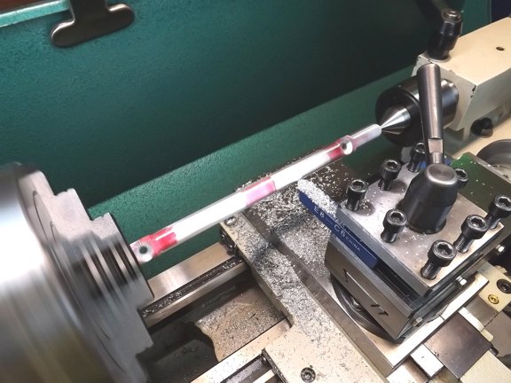
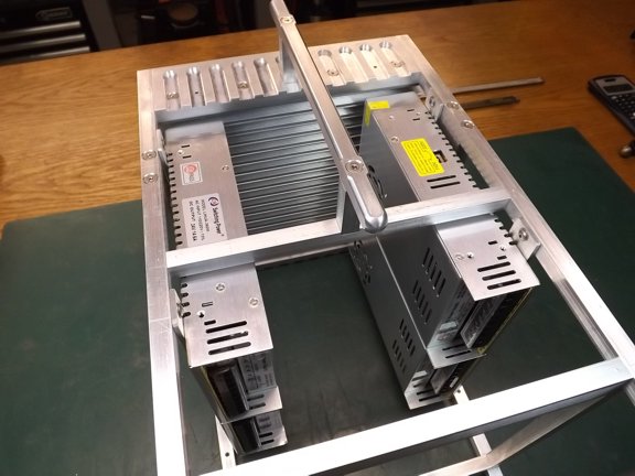
       I wanted to add a handle to the top of the light head for transportation so I prepared a piece of square stock in the lathe. I used a ball turning tool to round off the ends as seen above. I then used the 1/4-round bit to round over the sharp edges of the square stock.

       The handle will serve as a place to wrap the power cord as well as be a sturdy lifting point for the light head.

       The light head will be supported by a fixture yoke which will sit on top of a tripod. To make this happen I will need two mounting points set up on either side of the head. These were made up from 1/2” x 1-1/2” bars and machined to accept a 3/8-16 thread.

       I milled 3/4” wide slots in each side support to lighten then up a bit considering this light head will be heavy.

       I installed the side supports where I planned for the yoke to pivot from which was close to the where the center of gravity of the head would eventually be later on..

       The next step was to machine the power supply support brackets. These were made from 1/8” x 1” 6061 aluminum.

       M4 x 8mm screws were used to attach the power supplies to the brackets.

       I used 8-32 button head screws to mount the power supply brackets to the frame rails. A #29 AWG drill bit was used for the 8-32 tap and a #18 was used for clearance of the screw threads.

       I mounted four of the five power supplies so that air flow form the future cooling fan would be able to reach the heat sink. The last power supply needed to mount on the tail of the light so that the driver boards will have room in the middle.

       The next step was to provide a home for the 25 driver boards. To do this I prepared some driver trays made of 3/32” thick “GPO3” electrical grade fiberglass board. I really like working with this stuff as it is heat resistant and a very good insulator.

       I planned on putting five boards on each tier of the driver board rack...

       I used my band saw to cut the board (not shown) while using a vacuum to collect the dust (which will make you itch if you are sensitive to fiberglass).

       My belt sander was used to smooth out the edges of the board employing the vacuum as well (not shown).

       I drilled a series of holes so that cable ties could be used to secure the driver boards to the trays. Larger vent holes were also drilled to help promote air flow through the driver’s heat sinks.

       The drivers could now be mounted to the trays with cable ties...

       To mount the drivers to the chassis I used 6-32 threaded rods and aluminum spacer tubes to stack the trays as seen below.

       Two cross support brackets were added to the chassis which now support the driver trays.

       The next step was to start setting up the outer sheeting of the light head. These were made with the 5052 aluminum sheeting (.063”) which was cut using my air shears.

       Once cut I used my belt sander to clean up any shear marks from the edges of the trimmed sheets (not shown).

       I prepared a hole for the 120mm cooling fan which will force air through the power supplies and then through the main heat sink.

<<< Previous Page

Next Page >>>

[Home] [What's New At RCDON] [Articles] [Aircraft Projects] [Aircraft Videos] [Aircraft Videos II] [Experimental Projects] [Experimental Projects II] [Nixie Tube Clock Project] [6CI Steam Engine Project] [Vertical Boiler Project] [The Toolroom Tune-Up Project] [The Reverse Tumbler Project] [Red Wing Engine Project] [MakerGear M2 Project] [The LED Studio Light Project] [My Collection] [RC Links] [About Myself] [Contact RCDON]