Sears Custom 10XL Project

<<< Previous Page

Next Page >>>

Page 7

       I applied some assembly lube to the roller bearings before setting the gears in place. This will prevent any dry friction before the oil can circulate after filling.

       I now place all of the gears in place with their shim washers at each end of the shafts as needed...

       Hopefully this will be the last time I will see these gears again ;0)

       The case was sealed up at this point with a light film of RTV sealer on the new gasket (not shown). I also dry fitted the gear selector with it’s new rubber seal boot (bottom left) that will keep water out of the case should it get rained on.

       The brake drum and brake band assembly was installed making the transmission ready for install into the tractor.

       At this point My goal was to get the tractor fitted out and running before I set up to paint the frame. It would be a a lot of work to take it apart again but will make for a much better build than fixing paint after needed modifications are discovered.

       I painted the exposed parts of the steel axles which could rust after the hubs are installed. I do this with all of my equipment including my new zero turn mower...

       I filled up the transmission with some 40 weight motor oil and checked for leaks (not shown). No oil on the floor so I bolted the hubs and wheels on to get the chassis back on it’s feet. Looks like a tractor again :0)

       At this point I test drove the tractor (not shown) to make sure all of the gears worked. I was really encouraged by it’s performance and ready to charge on toward the finish line :0)

       The next step was to engineer the starter generator control system for the tractor. I would need to figure out a way to actuate the compression release on the engine when the starter is actuated as well as control the starter/generator functions during normal operation. I drew up a schematic that would hopefully do the trick...

       I sourced up a bunch of parts from eBay and Amazon for this project as seen below. Notice the old school voltage regulator (silver box) of which I replace for a solid state one later on...

       I decided to use some vintage components to keep the old school look going with this build.

       I needed a clutch/brake switch (left) to act as a safety interlock with the starter to prevent the tractor from lurching forward during start up. I also needed a starter switch that would call for the starter to engage when the throttle lever is raised (right). Both were found used from eBay which is one of my favorite placed to hunt for vintage and used parts.

       The stock throttle lever needed to be modified to hold the starter switch so some brackets were made and welded into place...

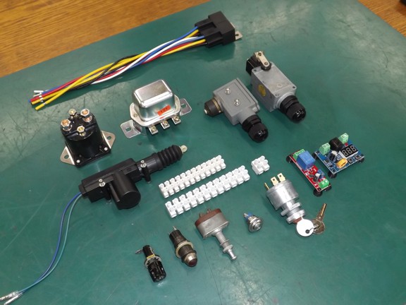
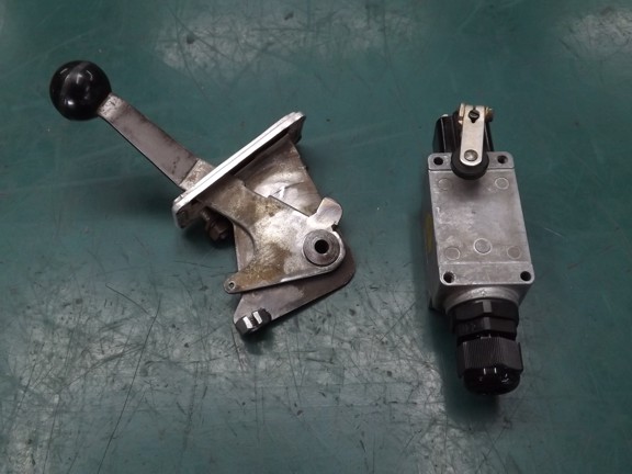
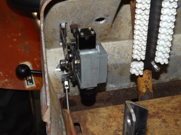
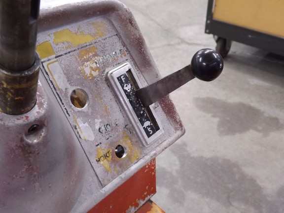
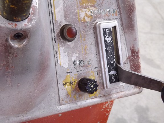
       The use of the throttle lever as a starter switch is a unique solution to starting and stopping the tractor. It will eliminate the need to push a separate start button as well as simplify stopping the diesel engine without adding a fuel solenoid to cut off the fuel supply. I would later find this setup quite enjoyable to operate, just roll up the throttle and go :0)

       Next I added a vertical support for the terminal blocks which was installed behind where the battery will sit. These will connect all of the system wiring to the vaious components...

       The throttle lever/switch was fitted to the instrument/control panel to test operation.

       I tested the locations of the charge indicator light and panel fuse as seen below. This is only temporary as I still have to paint the instrument panel and add new fiberglass placard backs (shown later).

       The top left push button is for the horn. Next to it is the light switch and below it the key switch...

       The clutch/brake switch was now set up to signal when the clutch is disengaged and the brake applied.

       I installed a new throttle cable that connects to the governor control linkage. This cable will allow the throttle lever to stop the engine when fully pushed down which eliminates the need for a fuel shutoff solenoid.

       I also installed a automotive door lock actuator to be used as a compression release to aid in starting the high compression engine.

       You can see how the control rod will pull the compression release lever down during startup...

       I installed the starter generator solenoid and charge regulator next to where the battery will sit and then made sure the battery would still fit...

       At this point I wanted to install the new LED headlights so they could be wired up as part of the electrical system. Before I mounted the grille housing to the chassis I wanted to install the new grille mesh I got from Amazon. This stuff is made from painted stainless steel which will last much longer than painted carbon steel.

       I used some 1/4-20 stainless screws to hold the new grille in and it was ready for mounting.

<<< Previous Page

Next Page >>>

[Home] [What's New At RCDON] [Articles] [Aircraft Projects] [Aircraft Videos] [Aircraft Videos II] [Experimental Projects] [Experimental Projects II] [Nixie Tube Clock Project] [6CI Steam Engine Project] [Vertical Boiler Project] [The Toolroom Tune-Up Project] [The Reverse Tumbler Project] [Red Wing Engine Project] [MakerGear M2 Project] [The LED Studio Light Project] [Sears Custom 10XL Project] [My Collection] [RC Links] [About Myself] [Contact RCDON]