 |
 |
|
 |
|
 |
|
 |
|
 |
|
|
 |
|
 |
|
 |
|
|
|
Posted on September 24, 2012:
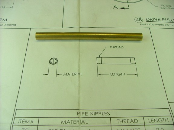
All right, back to the Red Wing project!!! This episode I will be working on the fuel filler neck and the fuel mixer. The fuel filler neck is made from a piece of .312” OD brass tubing that is included in the materials kit.
|
|
|
 |
|
|
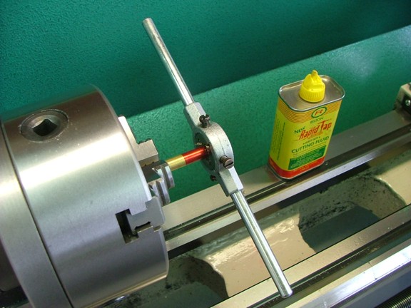
I began by threading one end of the tube with a 1/16-27 NPT pipe die to a depth of .300”. This time I used the lathe to help me thread the pipe at low RPM. Note: I always make sure that the die is tracking straight before I continue a thread on the lathe. It is easy to get the die started at an angle which will ruin the threads. I carefully watch the die handle to make sure there is no wobble when the chuck is turning...
|
|
|
 |
|
|
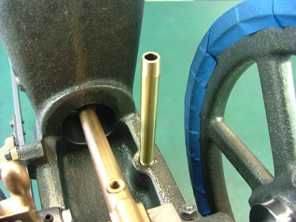
I removed the tube from the lathe and tested the fit in the engine frame. After looking at the length a bit I decided to cut the tube at 3” so it will be easier to access the filler cap (prints call for 2”). I then cut the tube and threaded the other side (not shown)...
|
|
|
 |
|
|
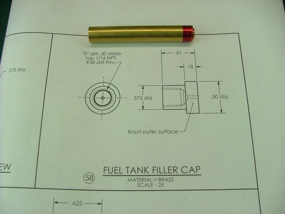
The next part to machine is the filler cap. This will be made from more of the 1/2” brass rod used earlier on the valve washers.
|
|
|
 |
|
|
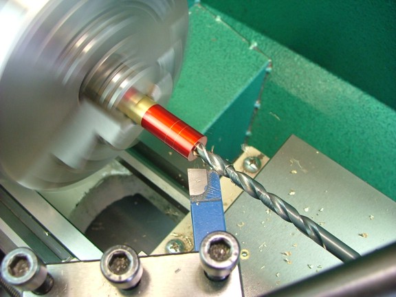
I first applied layout fluid to the end of the rod and laid out two lines at .330” and .510” from the end of the rod. I then bored out a 1/4” hole to .400” deep (for tap clearance - prints call for .300”).
|
|
|
 |
|
|
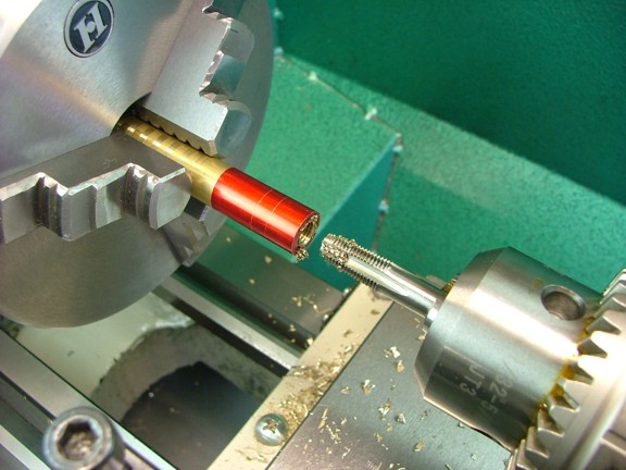
A 1/16-27 NPT “bottoming” tap was now used to thread the hole. I used the lathe’s VFD drive to power feed the tap into the brass. Luckily the drive will stall out (at low RPM) letting me know that the tap is at the bottom. Note: the tailstock of the lathe must be allowed to slide freely on the ways so that the tap can move into the part being tapped. I loosen the tailstock just enough to keep it from rocking on the ways...
|
|
|
 |
|
|
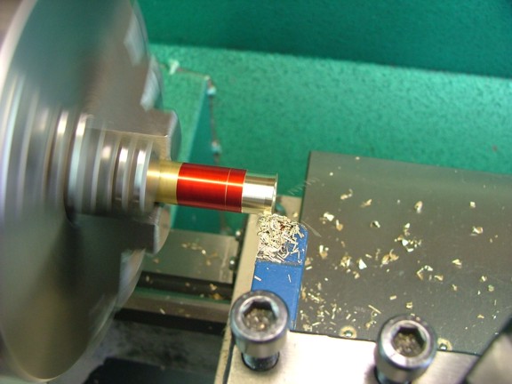
The next step is to turn down the neck of the cap to .375” up to the .330” line made earlier.
|
|
|
 |
|
|
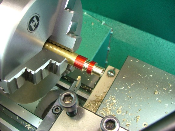
I now used my carbide parting tool to make a knurling relief groove at the top line (.510”)...
|
|
|
 |
|
|
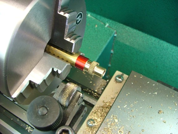
I set up my scissor knurling tool and formed a nice knurl on the head of the cap as seen below. I also used a tool bit to bevel the inside edge of the knurl to remove the rough edge at this time (not shown).
|
|
|
 |
|
|
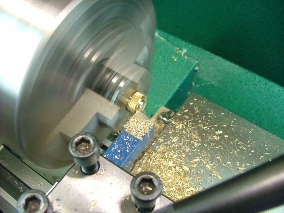
I now used my band saw to remove the cap from the rod and then trimmed the top of the cap down to the edge of the relief groove.
|
|
|
 |
|
|
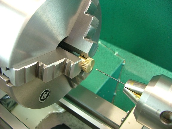
The last step is to drill out a #58 vent hole in the center of the cap...
|
|
|
 |
|
|
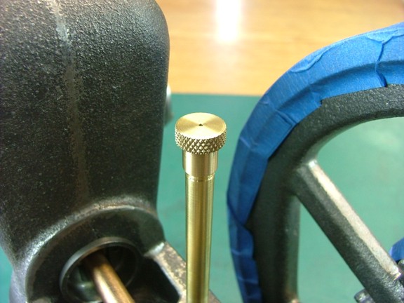
Not too bad ;0)
|
|
|
 |
|
|
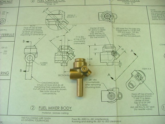
The next part to machine is the fuel mixer. The mixer body is made from a one-piece bronze casting that requires a good amount of machining to complete. I will start with the body and move into the smaller parts later on. Note: The mixer assembly is probably the most complex part on the engine. If the mixer is not machined correctly the engine will never run consistent so it is very important to take your time and be as precise as possible. If you make a mistake you can easily order a new casting and try again ;0)
|
|
|
 |
|
|
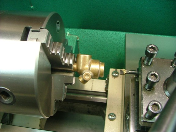
The first step is to mount the mixer body into the lathe using the chucking boss on the bottom of the body. I then set up a small carbide boring bar to widen out the “fuel orifice” at the top of the mixer.
|
|
|
 |
|
|
I carefully bored out the fuel orifice to .450” in diameter at a depth of about .400”.
|
|
|
 |
|
|
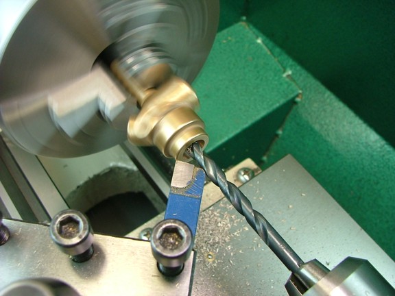
The next step is to drill a small divot on the bottom of the “L” shaped “induction port” inside the body. This is done so that a smaller drill bit can follow the center of the divot much like a pilot hole. I used a 1/4” drill bit to make the divot while using a tool bit to steady the drill. This can also be done with a long center drill or solid shanked pilot bit. I did not have either on hand so I used a standard twist drill with acceptable results...
|
|
|
 |
|
|
I drilled the divot hole to a depth of .030”. You don’t want to go much deeper than that...
|
|
|
 |
|
|
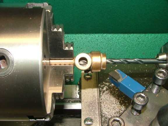
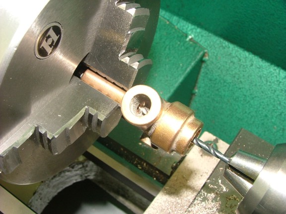
The next step is to drill a #31 hole to a depth of .500”. I made sure that the small drill was tracking straight before plunging it into the casting. Note: You can see the divot hole in the photo below...
|
|
|
 |
|
|
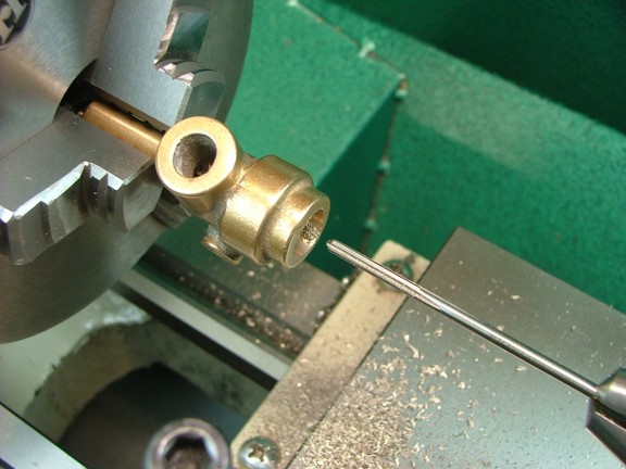
I now cleaned out the small hole with compressed air and then reamed the #31 hole with an 1/8” chucking reamer...
|
|
|
 |
|
|
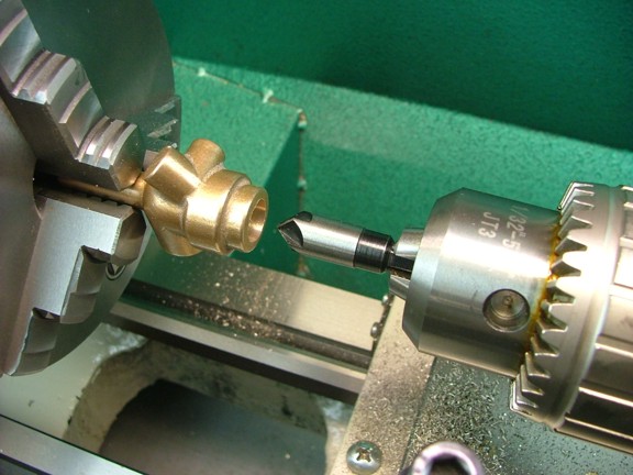
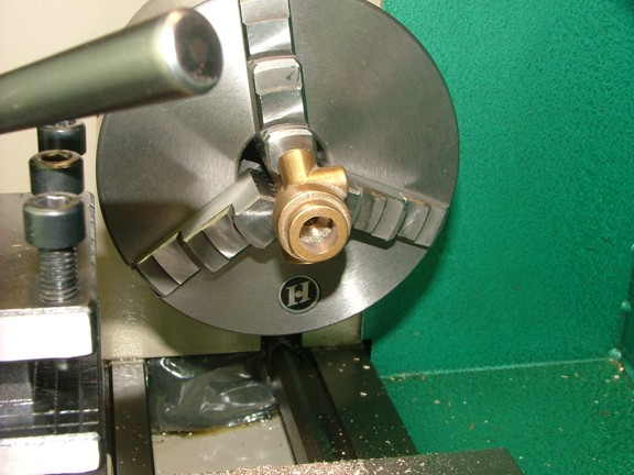
The next step is to countersink the mixer valve seat with a 90° countersink bit. I custom ground a cheap 1/2” wide countersink bit to fit exactly inside the .450” diameter port so that the top of the valve seat will be as wide as it can be. Note: You want the top OD of the seat to be as close to .450” as possible to allow for any deviance of the needle valve port (to be drilled later).
|
|
|
 |
|
|
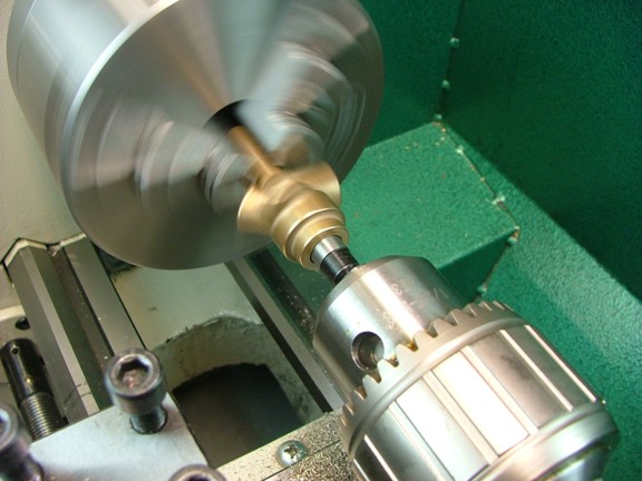
I cut the countersink into the mixer body in several increments. I checked between each cut to see how wide the top OD was to make sure I did not go too deep.
|
|
|
 |
|
|
You can see the finished seat below...
|
|
|
 |
|
|
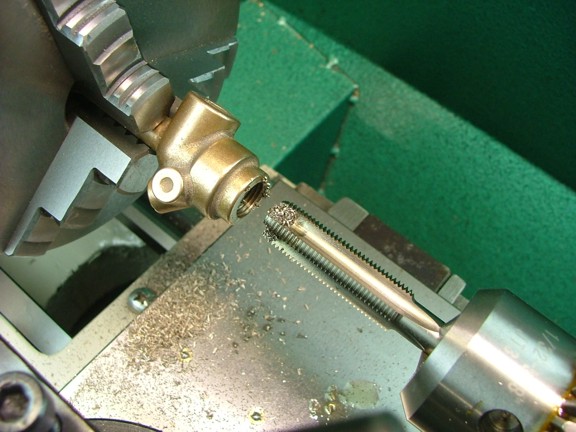
The next step is to tap the 1/2-20 threads into the top port of the mixer. I used a “bottoming” hand tap to make these threads. I was careful not to hit the valve seat with the tap of course...
|
|
|
 |
|
|
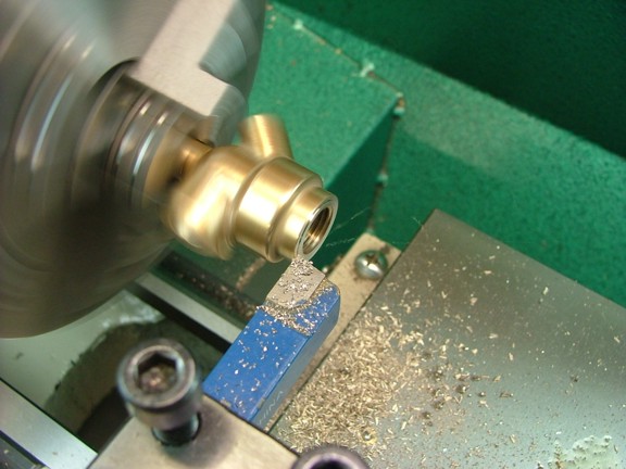
Now I can trim down the top neck of the mixer body to a height of .140” from the lower “step” of the body...
|
|
|
 |
|
|
 |
|
|
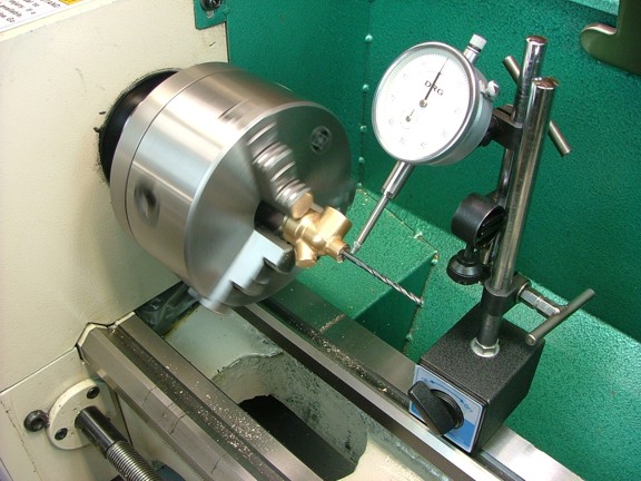
The next step in machining the mixer body is to cut the chucking boss off of the bottom of the casting at about .300” “down” from the induction port (not shown). I then loosely mounted the casting back on the lathe so that the chucking boss was sticking out of the chuck as seen below. An 1/8” rod (drill bit) was then inserted into the valve guide and used in conjunction with a dial indicator to center the casting in the chuck. Once all of the wobble was taken out of the alignment I was able to tighten down the chuck for the next operation.
|
|
|
 |
|
|
Next I trimmed down the valve guide/chucking boss so that the mixer casting was 1.438” in total length as the prints require.
|
|
|
 |
|
|
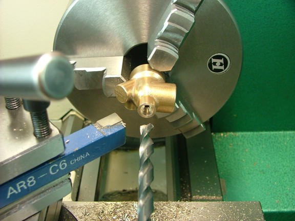
The next step calls for a counterbore of the valve guide hole at a diameter of .281”. I did not have a counterbore bit of that size so I used a regular 9/32” twist drill to bore a hole .200” deep into the valve guide. The angled seat should be OK as this hole only serves as a valve spring pocket.
|
|
|
 |
|
|
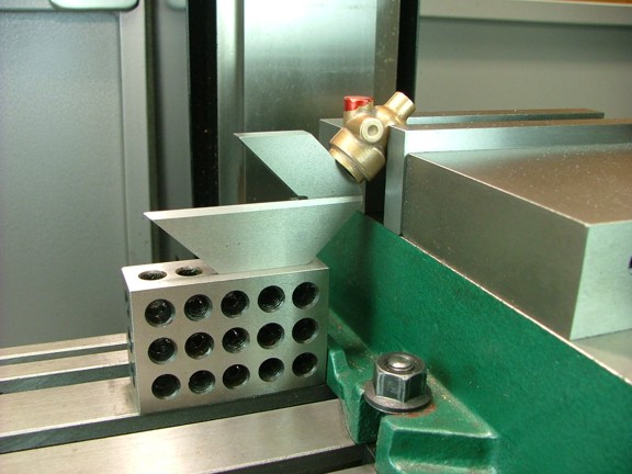
I now moved the casting over to the milling vise and mounted it so that the fuel orifice was at 45° to the table. You can see how I used a round stock center finder to align the casting in the vise...
|
|
|
 |
|
|
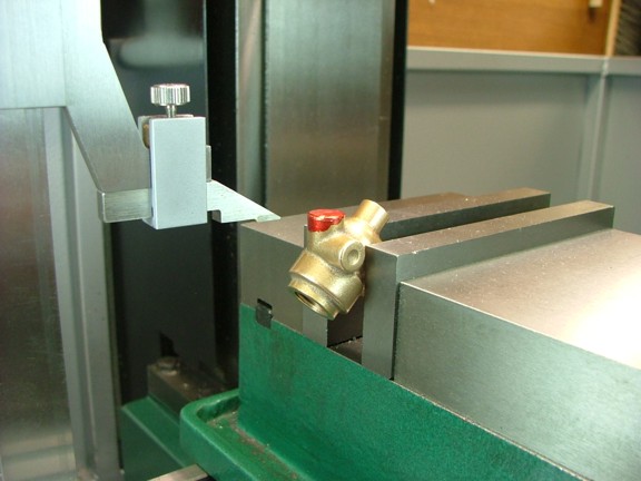
The next step is to find the height of the center of the fuel line port on the side of the casting. I measured the height of the port’s center with my height gauge and then moved the gauge up .380” so that I could scribe the side of the needle valve boss as seen below. This line will help me trim the boss to the correct height.
|
|
|
 |
|
|
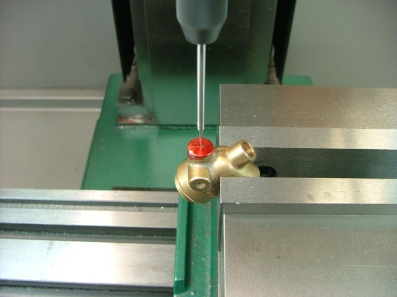
I now centered the spindle over the needle valve boss and zeroed out the table for future reference...
|
|
|
 |
|
|
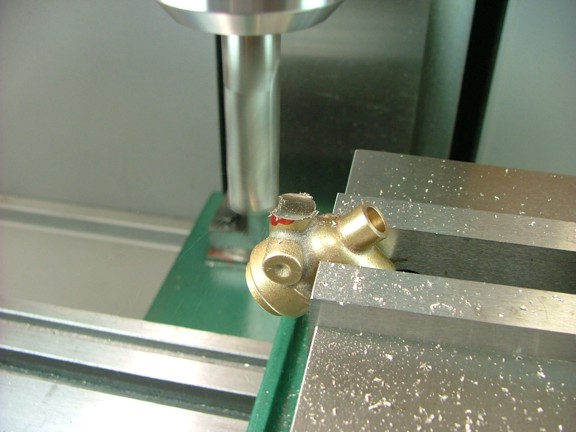
Next I used a 1/2” end mill to trim down the boss to the line I scribed earlier.
|
|
|
 |
|
|
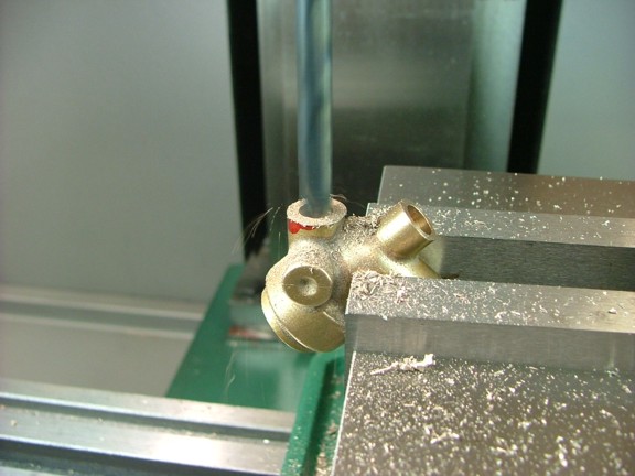
I now returned the table to the zero reference and then spotted a hole in the center of the needle valve boss with a #2 center drill (not shown). I then followed the CD with an “I” sized drill bit (.2720”) to a depth of .438”...
|
|
|
 |
|
|
The next step is to tap the hole with a 5/16-24 bottoming tap. Note: I used the digital depth gauge on my mill to make sure the tap did not hit the bottom of the hole...
|
|
|
 |
|
|
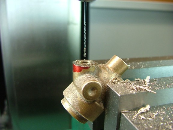
I now cleaned out the threaded hole and installed a #65 drill bit (.035”) into the chuck of the mill. I then carefully drilled a hole straight through to the valve port. Note: I did not need to use a center drill as the point of the “I” twist drill hole was sufficient to center the #65 bit...
|
|
|
 |
|
|
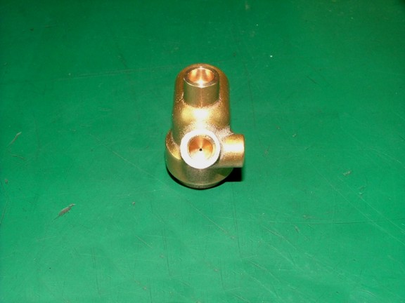
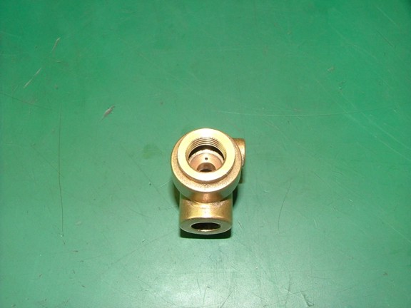
You can see the finished needle valve port in the photo below...
|
|
|
 |
|
|
You will notice that the needle valve hole is in the center of the valve seat (below). This is to allow the mixer valve to stop the flow of fuel when the engine is not drawing air through the mixer. If this hole is offset too much to either the inside or outside of the seat it may leak fuel...
|
|
|
 |
|
|
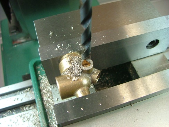
The next step is to drill out the fuel line port on the side of the mixer. I centered up the spindle over the fuel line boss and drilled a 1/4” hole to a depth of .313”. Note: The prints call for a “D” drill but a 1/4” will work as well.
|
|
|
 |
|
|
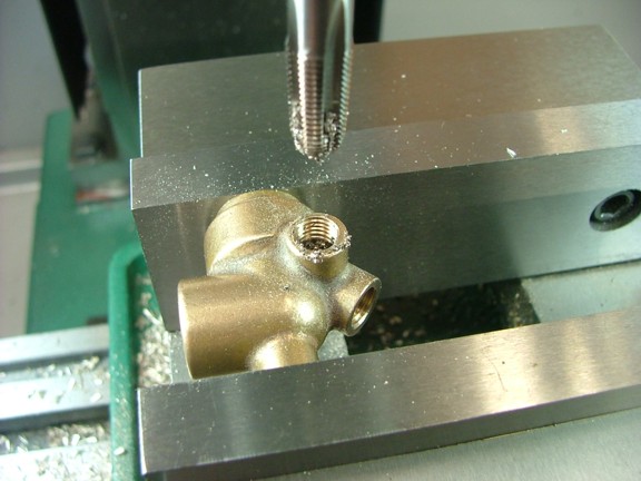
Now I tapped the hole with a 1/16-27 NPT hand tap...
|
|
|
 |
|
|
I now finished off the job by drilling a 3/32” hole in the center of the port. I stopped the drill once it breached the side of the needle valve port.
|
|
|
 |
|
|
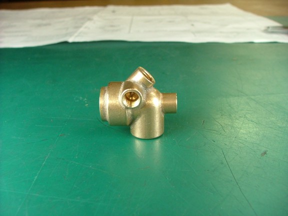
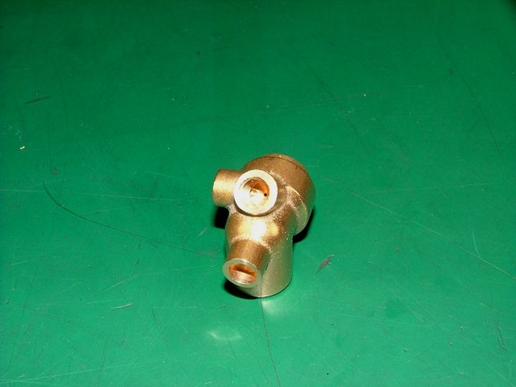
The fuel mixer casting is now fully machined. I ran the finished casting through the tumbler to polish it up a bit and then cleaned it with Brakleen (not shown).
|
|
|
 |
|
|
You can barely see where the fuel line port intersects the needle valve port in the photo below...
|
|
|
 |
|
|
I am making good headway although there are few more intricate parts to make. Check back again for the next installment of the Red Wing project when I tackle a few more mixer parts and get closer to completion.
Till then my friends!!!
Don R. Giandomenico
|
|
|
 |
|
 |
|
 |
|