 |
 |
|
 |
|
 |
|
 |
|
 |
|
|
 |
|
 |
|
 |
|
|
|
Posted on September 22, 2012:
Hello folks!! I am excited to get back to work on the Red Wing engine. This episode I will be working on the guide plates and latch out bar. The pushrod guide plates are made out of a piece of 1/8” x 3/8” brass bar that is included in the materials kit (seen below).
|
|
|
 |
|
|
I started out by laying out the two holes on the “front” (head side) guide plate at .200” and .400” from one end of the brass bar. I then lined up the spindle on the first hole.
|
|
|
 |
|
|
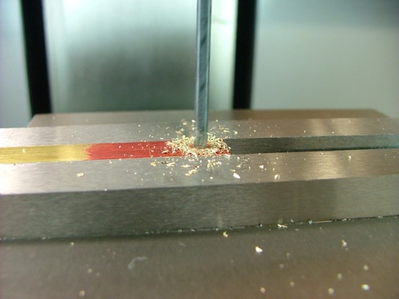
I drilled out the two holes with a #32 drill bit and then cut the bar to a length of .800” for fitting on the engine.
|
|
|
 |
|
|
I mounted the bar (layout fluid side “in”) to the head with a set of 3-48 “bolts” that were included in the hardware kit. I then used my scribe to mark out where the pushrod guide boss’s edges meet the guide plate (from behind).
|
|
|
 |
|
|
I now removed the bar which revealed the shape needed for the guide plate...
|
|
|
 |
|
|
I trimmed down the guide plate to resemble the cut lines with my belt sander and then remounted the plate for a fit check. Note: I did not follow the prints to a tee as they show more “scroll” work in the plates. I chose to use a simple bevel/radius design that I like better...
|
|
|
 |
|
|
The next step is to make the rear guide plate.
|
|
|
 |
|
|
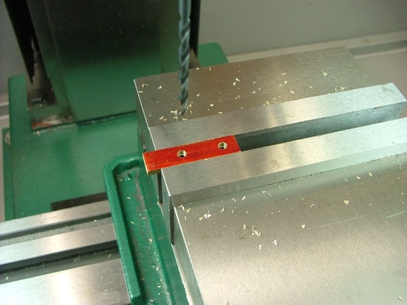
I laid out two holes at .250” and .938” from one end of the remaining bar stock and then drilled them with a 9/64” drill bit...
|
|
|
 |
|
|
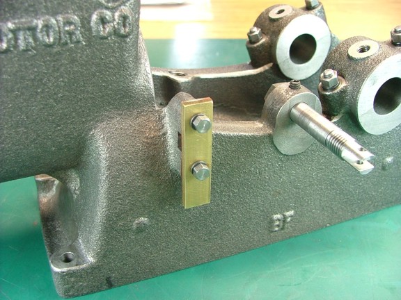
I bolted the rear plate to the engine frame (layout fluid side “in”) and scribed the top edge of the plate for cutting. I then turned the plate upside-down so that the bottom side could be scribed in the same way.
|
|
|
 |
|
|
I removed the brass bar and used the belt sander to contour the ends of the guide plate as I had before. I then remounted the plate so that I could scribe the guide boss that hangs below the plate...
|
|
|
 |
|
|
I now used my Dremel tool to contour the bottom of the rear guide boss to match the new guide plate.
|
|
|
 |
|
|
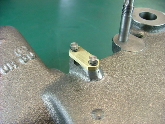
I remounted the guide plate and then used a center punch to identify the plate’s orientation to the frame as seen below.
|
|
|
 |
|
|
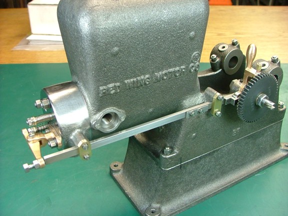
I now assembled the push rod on the engine frame and then checked the alignment of the rocker arm. I set the pushrod follower over the set screw side of the cam and then trimmed the push rod’s length so that the valve adjustment “bolt” was at it’s mid point of adjustment.
|
|
|
 |
|
|
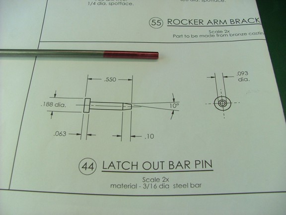
The next part to machine is the latch out bar pin which is made from more of the 3/16” steel rod...
|
|
|
 |
|
|
I marked the rod at .487” back from the end and then turned down the rod to .093” up to the line.
|
|
|
 |
|
|
I now cut a small lead-in bevel on the end of the pin as seen below...
|
|
|
 |
|
|
I removed the rod from the lathe and then cut off the pin side on my band saw (not shown). I then trimmed the head to a thickness of .063” on my small lathe to finish off the part.
|
|
|
 |
|
|
The prints do not call for a cotter pin hole however you may choose to add one if the pin has the tendency to “walk” out of it’s hole later on. This pin is snug enough that I am not too worried about losing the pin...
|
|
|
 |
|
|
The next part to machine is the latch out bar. This part is made from a bronze casting that is included in the basic kit.
|
|
|
 |
|
|
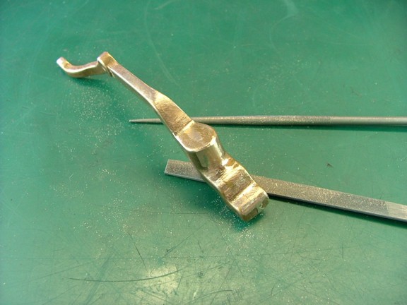
The first step I chose to perform is to file off the molding flash and sprue from the casting. After I was happy with the rough finish I carefully brushed the surface with a fine wire wheel on my bench grinder to smooth out the texture (not shown). Once again I choose to do this before the part is machined so that I cannot damage any newly machined surfaces.
|
|
|
 |
|
|
At this point I decided to fine tune the bar where it fits into the timing gear shaft.
|
|
|
 |
|
|
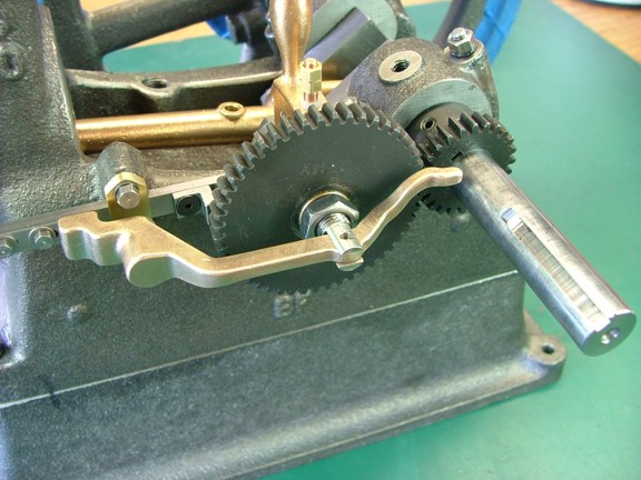
I carefully filed the thickness of the latch out bar so that it fits snug into the gear shaft to ensure a proper fit before machining.
|
|
|
 |
|
|
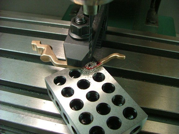
The next step is to drill out the pivot point of the bar. I clamped the bar to a 1-2-3 block and centered the spindle over the pivot center that is cast into the part. I then drilled out the hole with a 3/32” drill bit...
|
|
|
 |
|
|
A quick test fit on the engine and we are ready for the next step.
|
|
|
 |
|
|
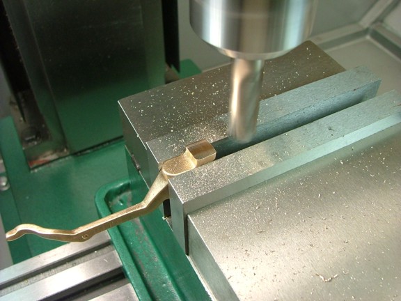
I set up the bar in the milling vise so that I could mill the bottom of the latch out pawl to a height of .160” from the lower step (to the left of the pawl).
|
|
|
 |
|
|
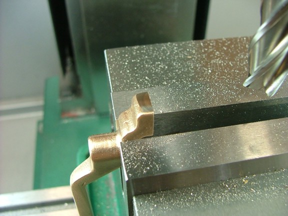
I now milled the end of the pawl to a depth just deep enough to clean up the casting as seen below.
|
|
|
 |
|
|
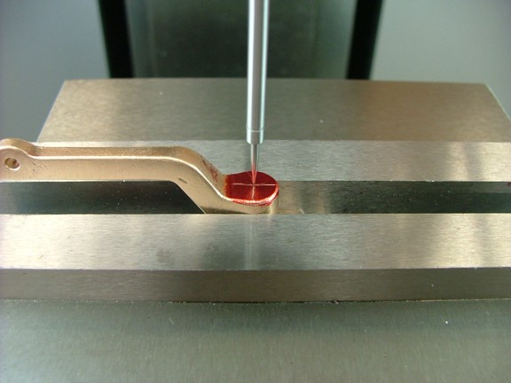
The next step is to drill and tap the adjustment screw hole in the latch out bar. I centered up the spindle over the screw boss as seen below...
|
|
|
 |
|
|
I now drilled the hole with a #21 bit...
|
|
|
 |
|
|
I followed the bit with a 10-32 tap as seen below. You will notice that most of these operations were done with the arm of the bar squared to the jaws of the vise.
|
|
|
 |
|
|
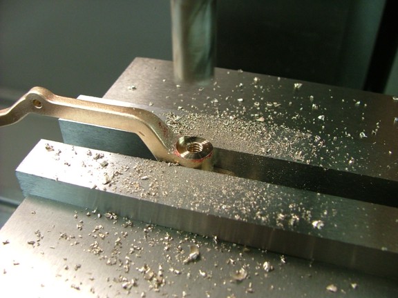
The next step is to spot face the hole with a 3/8” end mill...
|
|
|
 |
|
|
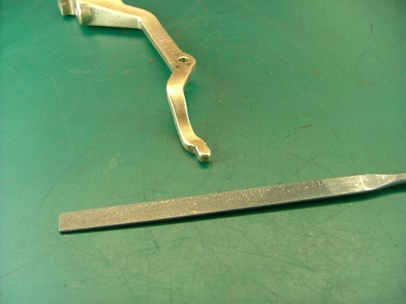
The last step is to carefully file the end of the arm so that it fits the shift collar’s groove.
|
|
|
 |
|
|
I filed the end of the bar in increments while checking the fit on the engine until the arm moved freely in the collar along it’s entire transit...
|
|
|
 |
|
|
The next part to machine is the adjustment screw. The screw is made from more of the 3/8” steel rod that was used earlier...
|
|
|
 |
|
|
I started off by scribing the rod at .500” from the end and then turning down the rod to a diameter of .186” up to the scribed line.
|
|
|
 |
|
|
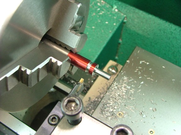
I now used my carbide parting tool to cut a knurling relief groove at .125” up from the bottom of the head. This will allow the knurling tool to get a better bite on the head of the screw.
|
|
|
 |
|
|
The next step is to test the diameter of the rod with the knurling tool to see if it matches the dies correctly for a good knurl. I flipped over the 3/8” rod and tested the knurling dies on the shaft to see if they will “track” correctly and not “double” up the pattern which will ruin the knurl. After a test knurl I decided to cut down the diameter of the screw head to .370” which seems to work best with this set of dies.
Note: It is important to test every knurling tool with the diameter of the part being knurled so that an optimal pattern is achieved.
|
|
|
 |
|
|
I applied some cutting oil to the screw head and then started to knurl the screw head at low RPM. Note: I am using a set of “scissor” knurls which help reduce the pressure needed in feeding the tool into the workpiece. On this part I had fed the scissor knurl into the screw head directly without any carriage movement. On longer workpieces I use the carriage feed to draw the tool along the part in several passes. I also angle the knurling tool slightly so that the side of the teeth can bite into the metal more efficiently.
It is a good idea to check the progress of the knurl at intervals to make sure the tool is still knurling and not grinding up the work piece. This can happen if the tool is used for too long...
|
|
|
 |
|
|
After the knurl was complete I used a tool bit to bevel the inside of the knurl as seen below...
|
|
|
 |
|
|
And now to thread the screw with a 10-32 die...
|
|
|
 |
|
|
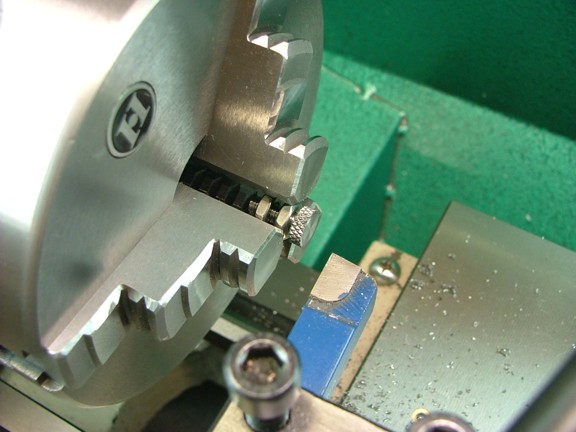
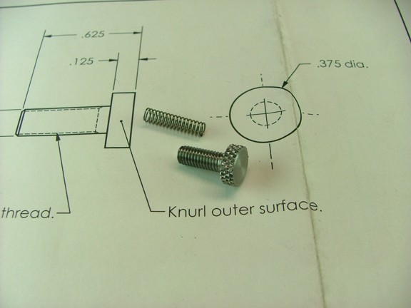
I cut the rod free from the screw head and then mounted the screw back into the chuck using a set of 10-32 nuts to support the screw (seen below). I then trimmed off the screw head and beveled the edge to finish off the part.
|
|
|
 |
|
|
 |
|
|
I now gathered up the adjustment screw and spring (supplied with the basic kit) and installed them in the latch out bar as seen below. Note: I am not sure but I believe that the adjustment screw is used for two purposes; one is to allow for minor adjustment of the RPM of the engine and the other is to provide some pressure against the governor linkage so that excess backlash is taken up.
|
|
|
 |
|
|
I decided to add a 10-32 undersized nut as a locking device so that the adjustment screw will not fall out while the engine is running. This undersized nut is not included in the hardware kit although it can be purchased from McMaster-Carr (Cat# 90730A411). Unfortunately they only sell them in a 100 count :0/
|
|
|
 |
|
|
I now assembled the flywheel onto the engine for a fit check and was pleased to see that everything fit beautifully ;0)
|
|
|
 |
|
|
I am having so much fun building this engine and cannot wait to see if it will actually run. Unfortunately this process is taking much longer than I anticipated due to the limited time I have to build and write. I do appreciate everyone’s patience in waiting for me to make progress on the engine and hope to have it running shortly.
Thanks again for all of the encouraging comments and please visit again for the next episode of the Red Wing Engine Project!!!
Till then, take care my friends!!!
Don R. Giandomenico
|
|
|
 |
|
 |
|
 |
|