 |
 |
 |
|
 |
|
 |
|
 |
 |
|
 |
|
|
|
 |
|
 |
|
 |
|
|
|
Posted on August 12, 2012:
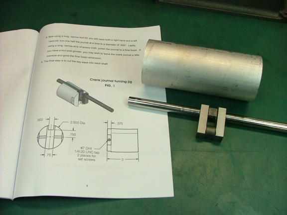
Hello again everyone!! This week I was able to get back into the crankshaft project. I still have yet to machine the crank pin and I will need to build a tuning jig to get the correct offset for the throw. Luckily the included engine manual has some tips on how to do this. I am all for using a proven method when there is one so I am going to follow the manual to build my jig.
The purpose of the jig is to properly support the crankshaft at the appropriate offset so one can use a lathe to turn the surface of the crank pin. If you have a lathe with a large enough four-jaw chuck you could probably do without a turning jig. My 6 four-jaw does not have a large enough throat to clear the protruding crankshaft so a turning jig is a good alternative.
|
|
|
 |
|
|
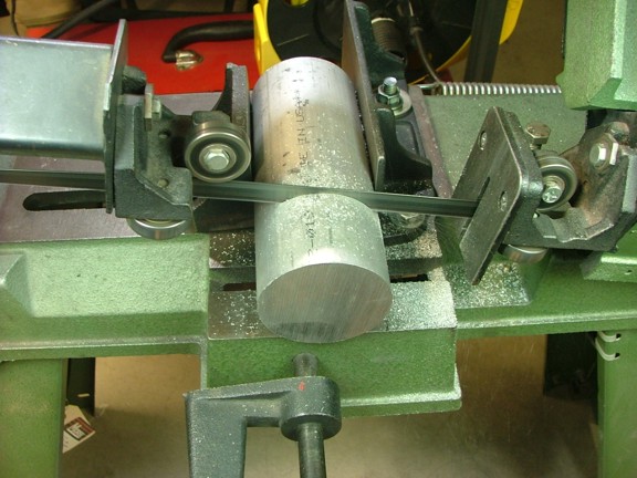
I started out by cutting down a piece of 2.5 diameter 6061 aluminum rod to 4.3 long (manual suggests 3). I added a little extra length to the jig to fully cover the length of the crankshaft end. Note: The aluminum rod is not included in the materials kit.
|
|
|
 |
|
|
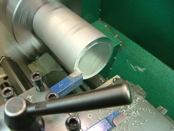
I faced both sides to get an overall length of 4.250.
|
|
|
 |
|
|
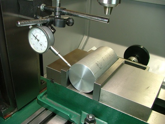
I mounted the rod in my 5 milling vise and squared up the vise with my dial indicator to ensure the rod is parallel with the travel of the table.
|
|
|
 |
|
|
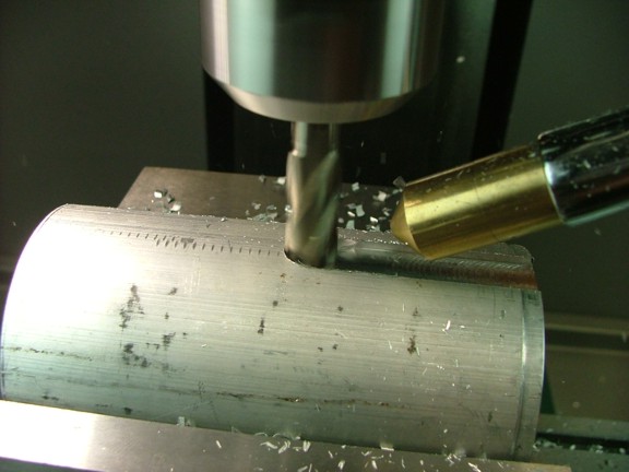
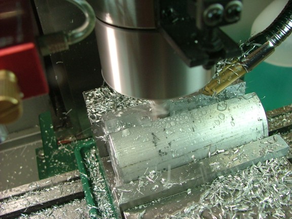
The next step is to mill out a .5 trough at .5 deep from the outer radius. I decided to cut a narrower trough with a 7/16 end mill at .450 deep on the first pass and then finish with a 1/2 end mill on the final pass.
|
|
|
 |
|
|
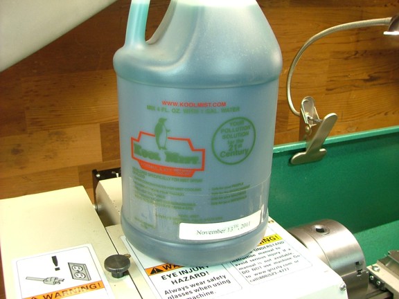
The aluminum rod was cutting quite gummy on the first pass so I decided to try out my new coolant misting nozzle. The misting nozzle uses a jet of air to propel a misting lubricant that cools the tool bit as well as lubricate the cutting process. I had yet to try it on aluminum so this was a good test. I will be using a product called Kool Mist which is a concentrated product that is diluted in distilled water (seen below).
Note: Since this misting product has water in it it is a good idea to coat your table and ways with a good rust inhibitor prior to using the solution. Displacing the water will keep rust from forming on your exposed metal surfaces.
|
|
|
 |
|
|
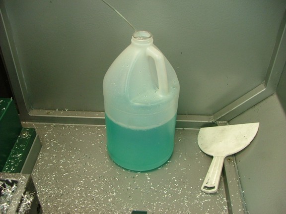
I diluted the lubricant and set up a jug with the suction clunk at the bottom (see the feed line below).
|
|
|
 |
|
|
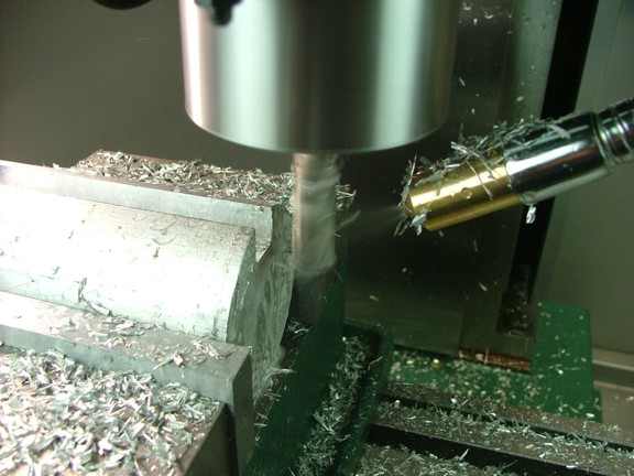
The misting nozzle I am using has a air and fluid adjustment so the droplets of coolant can be adjusted. I set mine up for a coarse spray pattern so the coolant/lube does not hang in the air and fog my shop up. I turned the system on and started cutting...
|
|
|
 |
|
|
I was happy to see that the misting system was making a huge difference on how the metal was chipping as well as keeping the channel clear of swarf. Although a bit messy with the fluid and all it is still a much better process than cutting the alloy dry.
|
|
|
 |
|
|
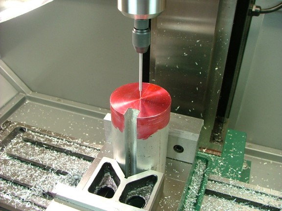
I finished off the 1/2 x 1/2 trough in the side of the rod and now was setting up for the .75 wide channel in the end of the rod as the manual shows. I laid out the center line on the rod and centered up the table with the wiggler tool.
|
|
|
 |
|
|
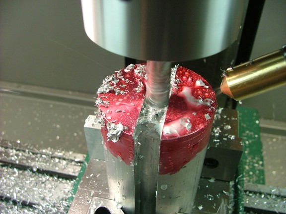
I made my first set of cuts with a 1/2 end mill to a depth of .350 as seen below.
|
|
|
 |
|
|
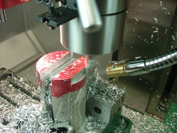
I now offset the table .125 (both left and right) to widen out the cut to a final width of .750 x .375 deep (not shown). I then offset the table 1.3 (from center line) to cut the outer flats for the set screws as seen below.
|
|
|
 |
|
|
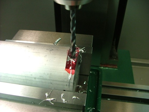
I spent some time cleaning up all of the coolant and swarf before moving on to the next step which was to drill out the holes for the set screws. I used a 13/64 drill bit to drill right through both sides of the jig. I then tapped the holes with a 1/4-20 tap (not shown).
|
|
|
 |
|
|
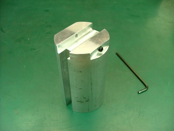
I installed a set of 1/4-20 set screws and I was done :0)
|
|
|
 |
|
|
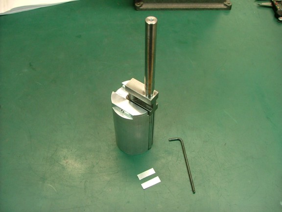
I cut out some pieces of thin aluminum sheeting to protect the finish of the crank as well as round off the faces of the set screws with a grinder. I then test fit the crank to see how I did.
|
|
|
 |
|
|
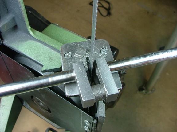
At this point I am feeling pretty confident that the jig will work so I proceeded to cut the support pillar out of the crank as seen below.
|
|
|
 |
|
|
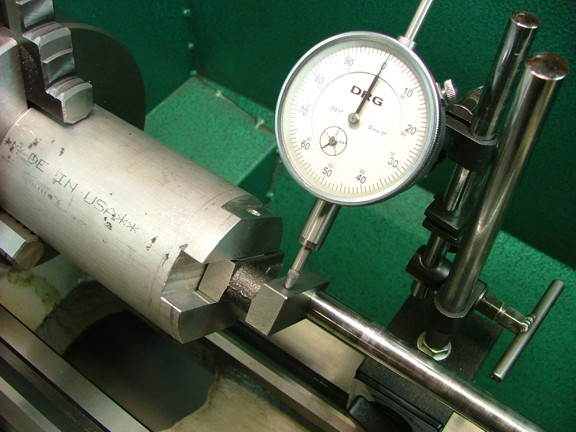
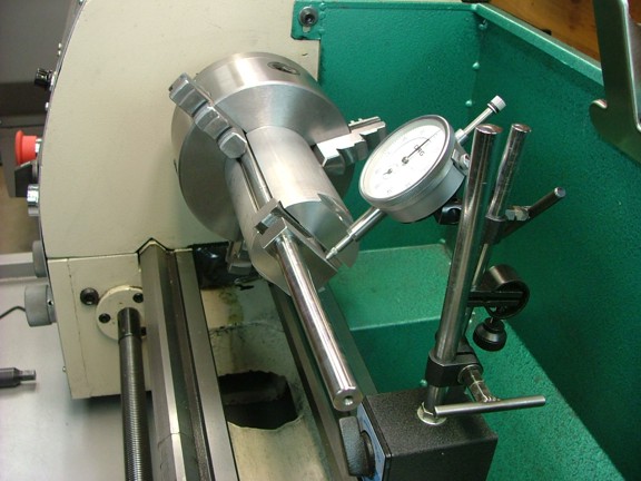
I set up the crank in the jig and used my dial indicator to center the throw arms between the sides of the jig as seen below. This will ensure that the crank pin or journal will be centered in the arms.
|
|
|
 |
|
|
Once both sides were equal distance from the axis I tightened down the set screws equally and then rechecked the alignment.
|
|
|
 |
|
|
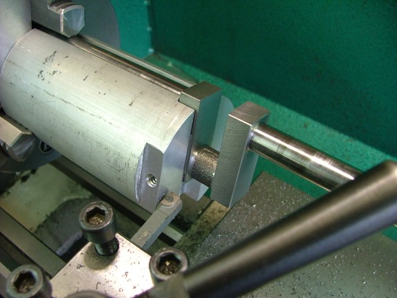
I started off by facing the sides of the arms so that they were .405 thick (prints call for .420). I narrowed the arms a bit to make up for a set of shoulders I will machine on the crank pin much like the ones on the outside of the arms (distance across the inside of the arms is .530 wide). This will ensure that the connecting rod will have clearance from the sides of the crank.
|
|
|
 |
|
|
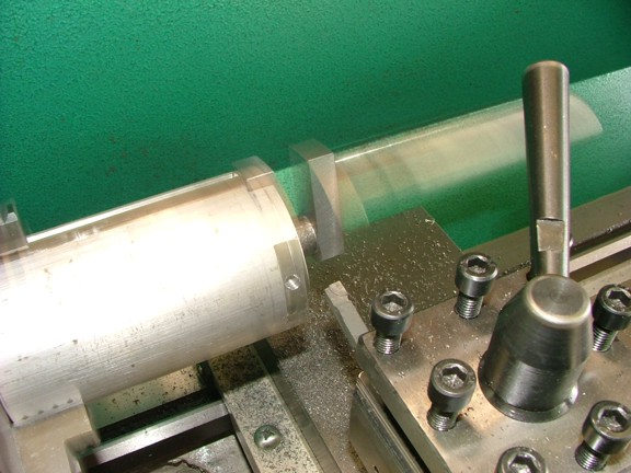
The turning jig was doing its job perfectly :0)
|
|
|
 |
|
|
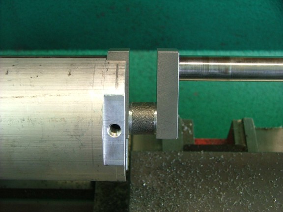
I stopped cutting the diameter of the crank pin at .635 which will be the outer diameter of the shoulders. If the casting is a bit off center you could go down to .560 if needed to get a clean surface.
|
|
|
 |
|
|
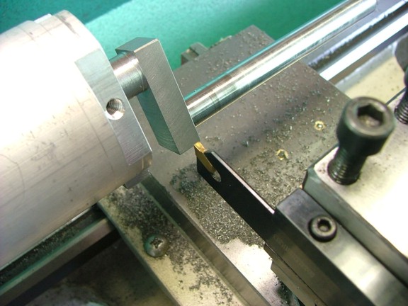
The nest step is to turn down the crank pin or journal to the 1/2 diameter the prints show. I used my .085 wide carbide parting tool to start cutting this portion.
|
|
|
 |
|
|
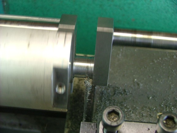
I carefully trimmed the pin down to .501 while leaving the shoulders at .015 wide. This step was critical so I was very careful not to make a mistake.
|
|
|
 |
|
|
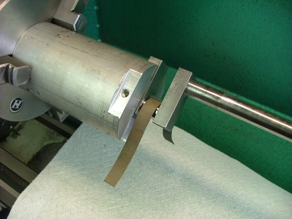
To finish off the last .001 I used some 320 grit sand paper. I measured the diameter frequently to ensure I did not go too far with the paper.
|
|
|
 |
|
|
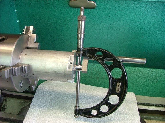
A final check with the micrometer and I was at .500 on the nose :0)
|
|
|
 |
|
|
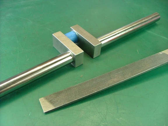
I removed the crank from the jig and taped up the finished journal so I could file the inside edges of the throw arms.
|
|
|
 |
|
|
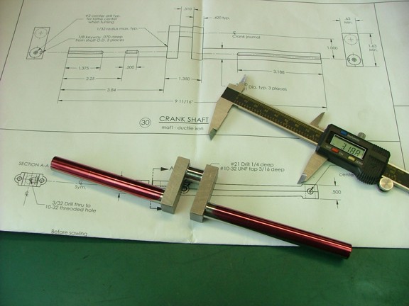
The next step was to cut the keyways into the crank as the prints show. I started this by laying out the cut endpoints on the shafts as seen below.
|
|
|
 |
|
|
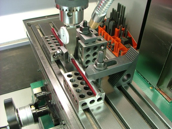
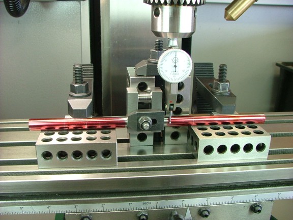
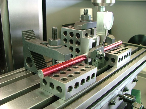
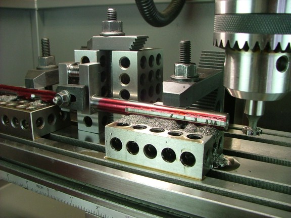
I set up the crank on the milling table using a set of 1-2-3 blocks as seen below. I then aligned the crank using a test indicator to ensure parallel alignment to the tables travel.
|
|
|
 |
|
|
You can see that I used one of the blocks to secure the throw vertically...
|
|
|
 |
|
|
I am now ready to start cutting.
|
|
|
 |
|
|
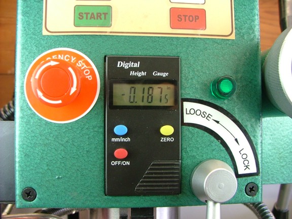
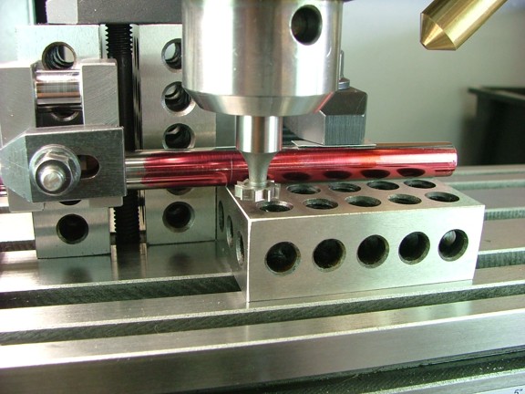
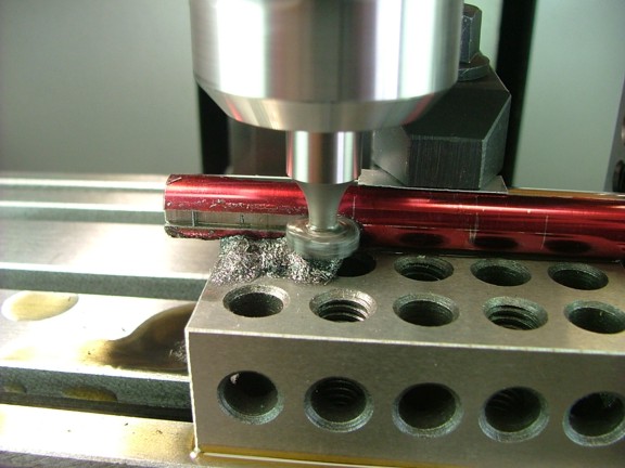
The prints seem to indicate the use of an 1/8 end mill to cut out the keyway slots however I have never had much luck with small end mills. I will be using an 1/8 keyseat cutter like the one I used for my 6CI Steam Engine build. I set the cutter in the chuck and zeroed out the depth indicator so that the cutter was bottomed out on the block under the shaft. I then raised the cutter .1875 to center the teeth in the side of the shaft.
Note: I must admit the digital depth indicator on my new mill is quite handy. I am not sure how I did without it on my smaller machine :0P
|
|
|
 |
|
|
I locked down the spindle and prepared for my first cut.
|
|
|
 |
|
|
I started on the left side of the crank to move the part into the rotation of the cutter and cut out the first of three cuts at about 200 RPM. The cast alloy was a bit tough to cut so I used a little cutting oil to help the process.
|
|
|
 |
|
|
I moved on to the last two cuts and finished the slots as required.
|
|
|
 |
|
|
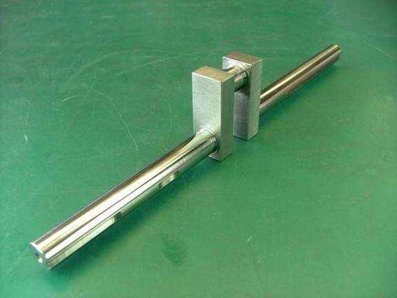
I cleaned off the oil and inspected the finished crank. Not too bad for my first one piece crank ;0)
|
|
|
 |
|
|
I am getting more excited about this build and cant wait to get into the next phase of the project which will be to machine the flywheels. I hope you can join me again for the next episode of the Red Wing engine project!!!
Till then take care my friends...
Don R. Giandomenico
|
|
|
 |
|
 |
|
 |
|