 |
|
|
 |
|
|
I placed the mill onto the bench and fitted four 6” x 3/8-16 bolts to secure the machine.
|
|
|
 |
|
|
I rolled the machine against the wall to admire my new setup....
|
|
|
 |
|
|
Because I may eventually be converting this machine to CNC control I have decided to add a CNC style “swarf cabinet”. This cabinet which will help contain the metal chips/coolant inside the tray and off of my workshop floor. To do this I used some of the 1” square tubing to frame out an enclosure while the machine was in place to insure a proper fit.
|
|
|
 |
|
|
I framed out the cabinet to be about 17” high above the chip pan and 56” wide at the outer edges. This should be wide enough to accommodate an X-axis stepper motor should I install a CNC kit later on. The Y-axis motor will probably hang out over the edge of the bench but there is not much I can do about that. Luckily I can add to this cabinet by welding on more square tube and adding sheet steel should I want more coverage later on.
|
|
|
 |
|
|
I built the cabinet to leave access to the column enclosure of the mill in case I need to access the “Z” axis lead screw or the electronics inside the enclosure. I will seal the 1/4” gap I left with some foam rubber so no metal chips can get behind the machine bench later on.
|
|
|
 |
|
|
The next step was to use the remaining 18 gauge sheet metal to finish the enclosure. I used TEK screws to temporarily mount each of the panels onto the cabinet frame as seen below...
|
|
|
 |
|
|
The two outer panels needed to be shaped to fit the miter cut frame so I used my sheet metal brake to bend two 45° bends in the sheets.
|
|
|
 |
|
|
I installed the side panels of the cabinet to see how they fit and was very pleased with the outcome :0)
|
|
|
 |
|
|
The next step was to seal the chip pan with the Bondo filler as I had done with the lathe bench earlier.
|
|
|
 |
|
|
I sealed the pan in several small applications as to not mix large amounts of the Bondo at once. I did not want to have a large batch “go off” before I could seal the edges and waste material....
|
|
|
 |
|
|
Once the filler had several hours to cure I was able to use my palm sander to clean up any rough edges on the fillets (not shown). I was then able to remove both machines form the metal pans and paint them with some Rust-Oleum “Hammered” finish silver paint (Cat #7213830). This paint is ideal as it is almost the color of the metal below the finish which will help hide all of the scratches that will inevitably happen later on.
|
|
|
 |
|
|
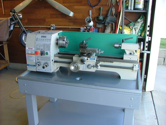
I let the paint cure for 24 hours before setting the machines back on the benches. You will notice that I also painted the workbenches with a latex semi-gloss exterior paint.....
|
|
|
 |
|
|
I set the lathe back onto the workbench and used some silicone sealant to seal the bolt holes that secure the lathe to the bench. The chip pan is now water tight and ready for any mess I can throw at it :0)
|
|
|
 |
|
|
I screwed down the milling machine’s chip pan and proceeded to install the outer covers which were also painted with the silver finish.
|
|
|
 |
|
|
I used a clear silicone sealant to seal all of the joints of the panels to prevent coolant or cutting oil from leaking out. This was applied before the panels were screwed on to insure a good seal.
|
|
|
 |
|
|
And now to install my beautiful new machine. I used some silicone sealant to seal around the bottom edge of the machine to prevent coolant from accumulating under the pedestal (this was applied with the machine raised up). I set the mill in place and then bolted it in. The swarf cabinet really makes this machine look professional ;0)
|
|
|
 |
|
|
I installed a set of drain fittings made from PVC and plumbed the drains to some two gallon containers (not shown). I also installed a set of Kobalt intermediate 3-drawer tool boxes on the bottom shelves for additional tool storage (I got them on sale at Lowe’s for about $120 each F.Y.I.).
|
|
|
 |
|
|
I decided to install a main disconnect switch up high as to prevent the little ones from switching on the machines when I am not around. I will later install a key switch for added safety...
|
|
|
 |
|
|
With the old shelving storage removed I am able keep the new benches within 12” inches of the original floor space taken up by the old shelving. This is important to me as I can still fit a car into the garage for service.
|
|
|
 |
|
|
You may have noticed the flexible steel hose pointed at the drill chuck (below). This is a coolant mist nozzle that I purchased on eBay for cutting steel. This system uses air pressure to mist a mixture of cutting solution and water at the tool bit which keeps it cool while cutting tough materials. I can also use the system with just air to remove metal chips from the work surface so I can see my work.
|