 |
 |
|
 |
|
 |
|
 |
|
|
 |
|
 |
|
|
|
Posted on June 22, 2012:
Hello again everyone!!! Since I’ve renovated my workshop I have been looking for a good project that will help me become more familiar with my new mill and lathe. These new machines are more complex than my old equipment and will require some time for me to get comfortable with. I figure that the best way to learn how to use these new machines would be to build another model engine so I have been on the hunt for a new kit. Lucky for me there are a ton of kits out there that range from simple to incredibly “involved” ;0)
My 6CI steam engine was a really fun engine to build and I have been looking for a similar kit to build with my new equipment. I really enjoyed reading the drawings and machining the castings to specification. So many intricate parts that needed to fit together perfectly. It was quite a challenge for my first “casting kit”. No doubt I will learn to use my new machines quickly if I get another kit like the 6CI.
Since I had such a good experience with the 6CI kit I decided to look at other similar models and found a really cool scale gasoline engine called the “Red Wing”. This model engine is a 1/4 scale version of a 5 hp “hit-and-miss” gasoline engine that was made in 1912. These types of stationary engines were used around the farm for things like driving water pumps and drag saws.
The 1/4 scale Red Wing gasoline engine is a fairly popular kit among the model engineering community with many videos and articles about the engine all over the web. This tells me that it must be a pretty good kit to work with and a great way to break in my new machines.
|
|
|
 |
|
|
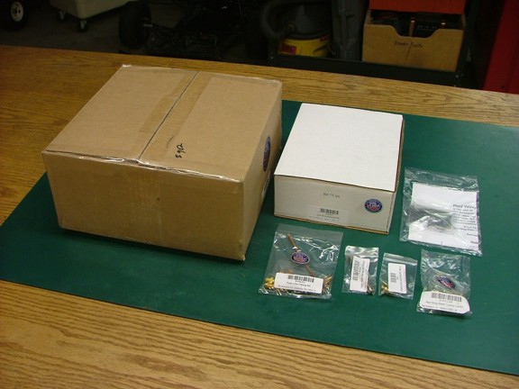
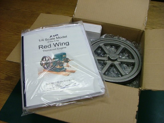
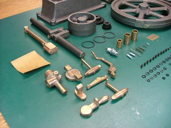
I decided to order one of the water cooled Red Wing kits from which showed up on my doorstep in nicely packed boxes. I was happy to see the same quality castings that I had encountered with the 6CI kit.
|
|
|
 |
|
|
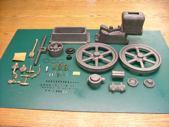
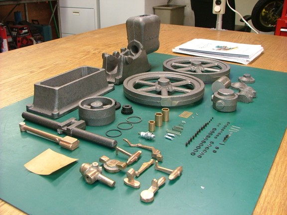
The basic kit comes with the following:
9 - Class-25 grey cast iron castings (frame, flywheels, etc...).
1 - Type 80-55-06 ductile iron crankshaft casting.
9 - Bronze castings (mixer, governor, etc...).
1 - 1.5” diameter class-30 grey cast iron rod (piston).
2 - Timing gears.
3 - Oil Lite bushings
1 - Set of piston rings and an oil O-ring.
1 - NGK CM-6 spark plug.
1 - Set of spilt lock washers, grub screws, cotter pins, springs, gasket material,
washers, O-rings, flathead screws and a roll pin.
1 - Red Wing Motor Co nameplate and rivets.
10 - Sheets of working drawings
1 - Supplemental information “manual”.
|
|
|
 |
|
|
The basic kit does not come with a “nuts and bolts” hardware package. My guess is that a lot of builders would prefer to machine all of their own nuts and bolts themselves. I like a good challenge every now and then, well... maybe not that tedious of a challenge :0P
|
|
|
 |
|
|
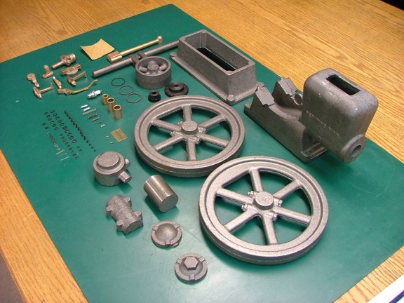
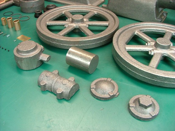
The castings seem to be free from defects although the molding sprue on the flywheels and head were aggressively removed in some places leaving low spots. Hopefully I won’t have to remove too much metal to clean them up.
|
|
|
 |
|
|
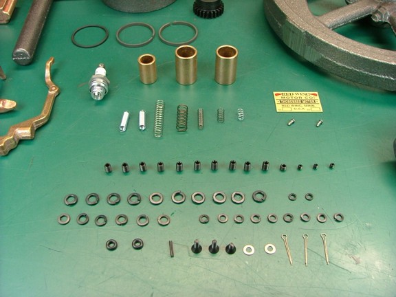
The hardware included below seems to be focused on items you would not normally make in a machine shop which makes sense...
|
|
|
 |
|
|
The castings are really clean and appear to have no surface defects.
|
|
|
 |
|
|
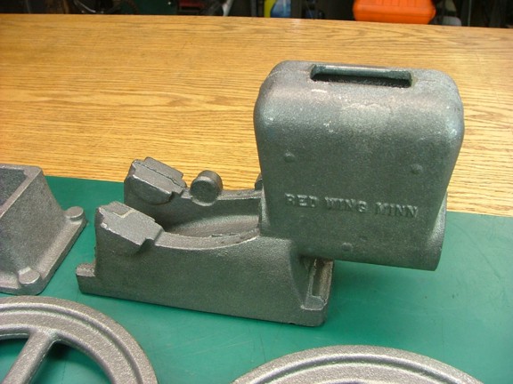
The main motor frame casting (below) is a pretty heavy piece. It will require me to learn a few new techniques to machine it properly.
|
|
|
 |
|
|
Overall I am quite pleased with my first impression of the kit although I wish it had come with all of the stock required to finish the build as the 6CI kit had. I guess this kit is targeted to the builder that has built a few different kits and has a lot of the raw hardware stock already on hand.
|
|
|
 |
|
|
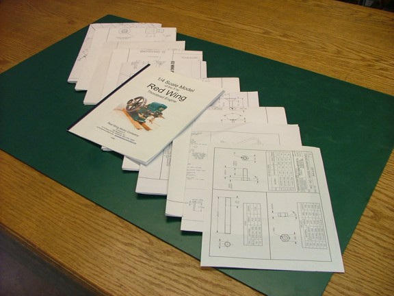
The Red Wing kit is furnished with a very nice set of working drawings including: 6 sheets of construction drawings for the engine, 1 general assembly drawing, 2 optional “buzz box” ignition system drawings, 1 fastener detail sheet and a supplemental guide to help with ideas on how to machine the kit. A lot of effort went into making these drawings which is obviously reflected in the hefty $550 retail price tag on this kit.
|
|
|
 |
|
|
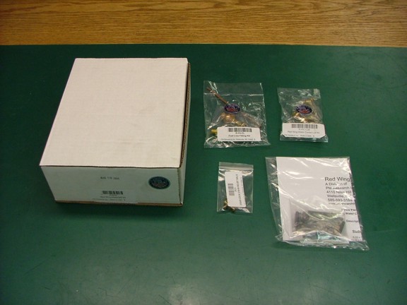
I decided to order a few additional supplies not included with the basic kit to complete the task a little quicker....
|
|
|
 |
|
|
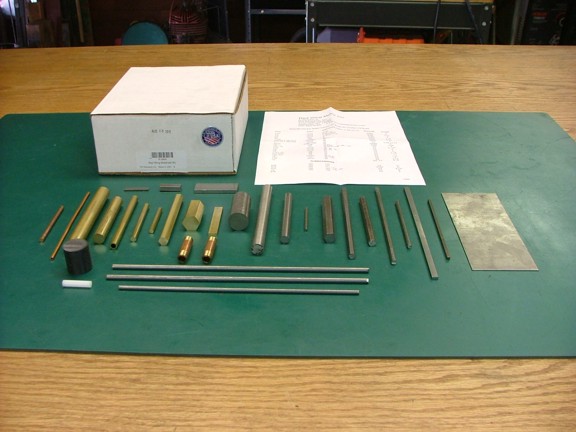
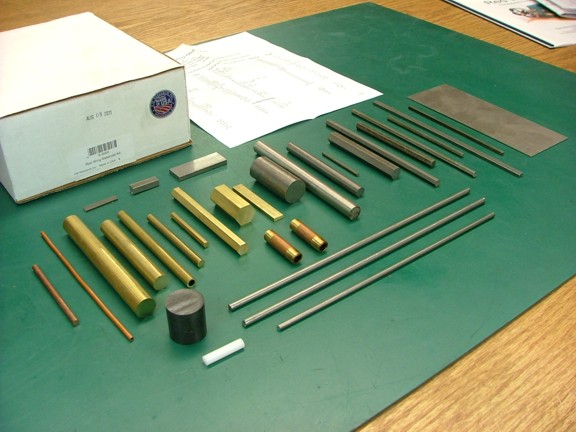
I am in short supply of model engineering stock so I opted to purchase the additional materials kit (Cat# R-BAR) for $75 (seen below). This collection has all of the raw stock to finish all of the nuts, bolts, screws, pins, axles, valves, washers, fittings and other parts (barring the drip oiler and drain valve assemblies). The kit comes with a parts list that cross references the drawing numbers with the type of stock used to make the part which is not always shown on plans.
|
|
|
 |
|
|
Ordering this stuff from suppliers at minimum lengths would cost a fortune so unless you have most of this stuff in the shop you may consider buying this kit.
|
|
|
 |
|
|
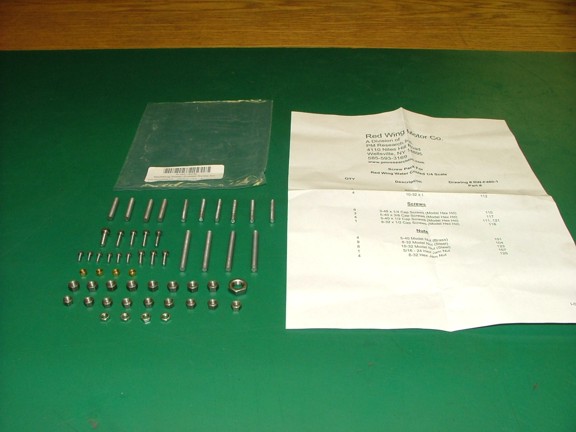
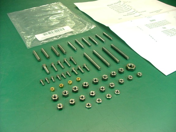
Even though the materials kit comes with the stock to make all of the hardware I decided to buy the screw assortment (Cat# R-WC-SCR) for $28.90.
|
|
|
 |
|
|
Some of these screws are really small and require a lot of patience to machine. Although I plan on trying my hand at threading these will save a whole lot of time which is most important to me these days.
|
|
|
 |
|
|
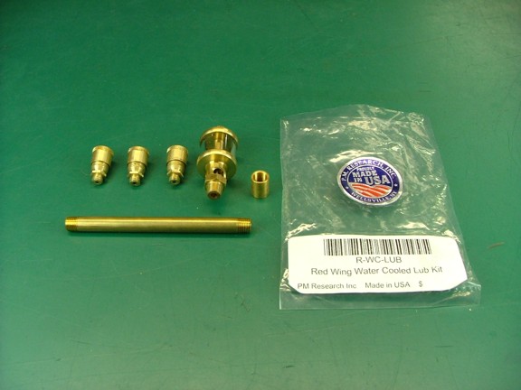
The next item I purchased is the lubrication kit (Cat# R-WC-LUB) which includes the ready to install drip oiler for $36.70. This is a really well made item and is totally functional.
|
|
|
 |
|
|
I also opted to buy the fuel line fitting kit (Cat# R-FK-FL) which features a beautiful globe valve that will compliment the finished engine ($38).
|
|
|
 |
|
|
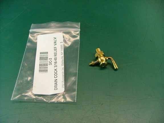
Last but not least I ordered a drain valve for the compression release (Cat# DC-3) for $27. This is not a required piece but adds a finished look to the engine.
|
|
|
 |
|
|
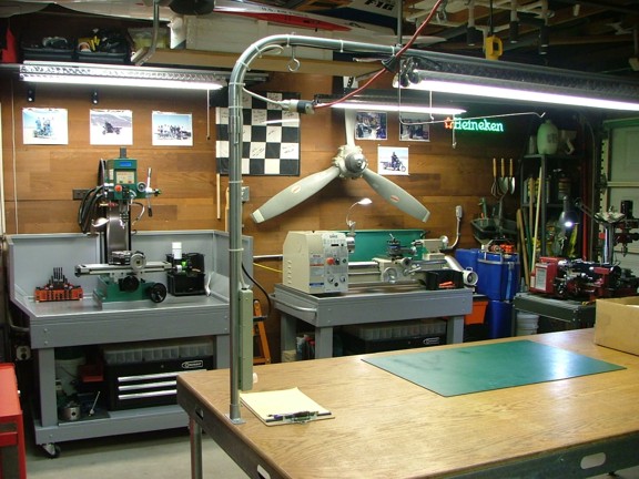
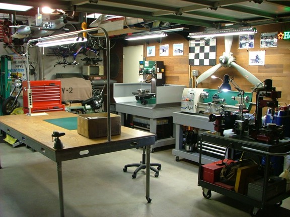
Now that I am prepared with all of my parts and drawings it is time to show you the equipment I will be using. I have been using a Central Machinery Micro-Mill and 7 x 10 Mini-Lathe for several years now which is what I used to build the 6CI Steam Engine kit a couple years back. For the most part I have been pleased with the performance of these machines but have been very limited in the size of parts I could machine.
I have always wanted larger capacity machines but did not know enough about the hobby to make a educated decision on what machines to buy. After some research on the hobby machinist sites I found the Grizzly line of machine tools.
|
|
|
 |
|
|
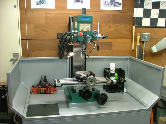
I purchased a Grizzly GO619 6 x 21 milling machine (seen below) which is a tremendous upgrade from my original mill. I custom built a bench and swarf cabinet for the mill as well as collected an array of new tooling for the machine. I should have a lot of fun learning to use this beauty ;0)
|
|
|
 |
|
|
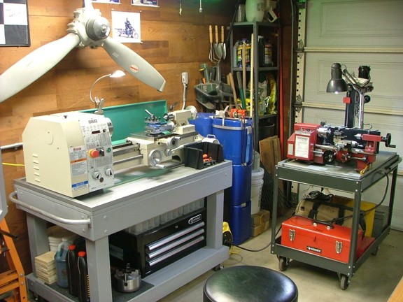
I also purchased a Grizzly GO602 10 x 22 metal lathe which is huge (below left) compared to the smaller Mini-Lathe (below right). I upgraded the motor to a three-phase VFD driven motor and added a reversing tumbler to the gearbox to enhance the lathe’s capabilities. Quite a capable machine.
|
|
|
 |
|
|
With my shop dialed in and all of my ducks in a row I am ready to start building!!!
Note: I must make clear that I am not a professional machinist. I am an electrician by trade and only have one engine casting kit under my belt. I have really no formal training with machine tools other than learning by trial-and-error. For the most part I will be learning as I go.
Nevertheless I’m sure that there will be better ways to machine parts than the methods I may choose. I am aware of that. This article is only my experience building this kit and not the “proper” way of approaching the build. Having said that I encourage those of you who may be attempting this build to try different methods and always remember that there really isn’t one “right way” to machine a part.
The key is to enjoy the process and learn everything you can. Also, don’t be to down on yourself when you make a mistake as they happen to the best craftsman out there. There are always replacement castings and as I always say, “you can fix anything made out of metal” ;0) Take in the experience and don’t rush anything!!! I have found that it is pointless to start one of these projects unless you are able to walk away when you are frustrated.
These kind of projects take time but in the end you will be amazed at what basic patience and careful actions will produce.
|
|
|
 |
|
|
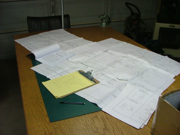
The very first thing I decided to tackle is to carefully study all of the prints. I think it is important to become very familiar with the prints and all of the parts you will be machining. I do this every time I start a new electrical job at work and I am guessing it will help me all the same in this project.
After I am comfortable with the drawings I start to catalog and acquire all of the additional tooling I will need during the build. You could choose to buy the taps and drills as you need them but I like to have it all ready so there is no wasted time. I would suggest buying a good wire gauge drill bit index if you don’t already have one. I would also suggest that you buy only high quality taps for this project. It would be a shame to break a cheap tap into a part that you have spent several hours machining on :0P
FYI: I have had the best luck with American made hand taps that I purchased through McMaster-Carr.
|
|
|
 |
|
|
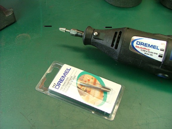
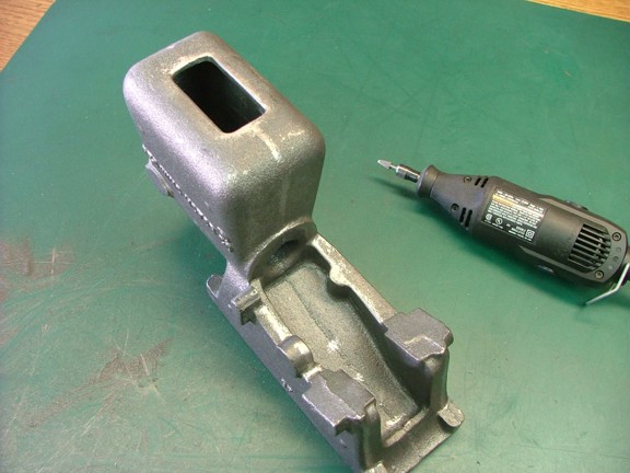
Now that I am ready with my tools I can begin cleaning up the castings with my Dremel tool. I like to use a Dremel #117 high speed cutter to clean up all of the molding flash on all of the castings before I put finished surfaces on them. This is to ensure that I don’t slip and destroy a nicely machined surface later on.
|
|
|
 |
|
|
The Dremel tool makes quick work of the molding flash and with a little practice you can blend the cast surface to look seamless. Of course it takes a whole lot of patience and may require a few “sittings”.
|
|
|
 |
|
|
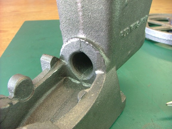
The high speed bits only last a little while due to remaining casting sand in the metal’s surface. I used about three of the #117 bits to finish all of the castings.
Note: I only cleaned up the surfaces that would not be machined later on.
|
|
|
 |
|
|
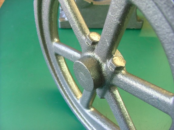
The flywheels feature a set of mock clamping bolts that surround the hub. I am not a big fan of nonfunctional parts on a model but I can see how they add a scale look to the flywheels.
|
|
|
 |
|
|
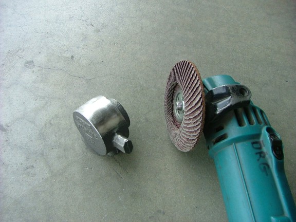
I used a 36 grit flap-disk to clean up the head casting where the molding flash was removed. I had to grind down quite a ways to clean up the grinder marks left by the foundry.
|
|
|
 |
|
|
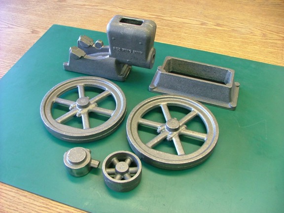
The process took about 2.5 hours to complete and required a bunch of patience. It should pay off in the end with a beautifully finished engine I hope.
|
|
|
 |
|
|
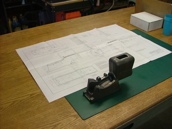
Now that I am ready to do some actual machining I will start with the engine frame. I restudied the prints and then worked out a game plan to figure out what to machine first. The included “manual” has some tips on how to go about doing this and they all make sense so using the guide as a basis I prepared for my first operation.
|
|
|
 |
|
|
Now it’s worth mentioning that castings can vary in size and shape depending on when they were produced and by whom so it is important to get a good idea of where the part will be referenced by the drawing. By that I mean if the casting is 6” tall and the machined part is 5.75” tall you must determine where to cut off the excess metal.
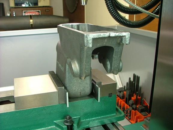
After studying the prints a bit more I decided to reference the engine frame off of the base of the casting and all subsequent measurements will be made off of this “0” reference. I mounted the frame hopper down in my 5” mill vise with a couple of parallels to clear the bumps that are cast into the sides of the water hopper (seen below).
The manual suggests milling down a flat surface on the top of the hopper to assist in this procedure although I don’t like the idea of messing with the finish of the casting so I will do this without milling.
|
|
|
 |
|
|
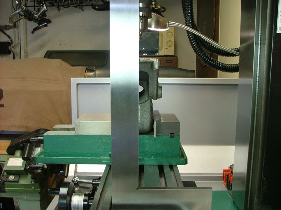
To make sure the casting is as “square” as possible I decided to use two sharpie marker reference marks made on the casting seams at the top of the hopper and on the base. I then used a large machinist’s square to visually sight these marks to align the casting vertically (seen below). This could of been done several ways but I am pretty happy with this method.
|
|
|
 |
|
|
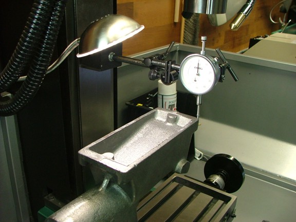
Now that the casting is vertical in the “Y” axis I needed to check level it in the “X” axis. I used a dial indicator to roughly measure the difference in height from the back side to the front (seen below). I was really close so I tightened the vise and rechecked all measurements.
|
|
|
 |
|
|
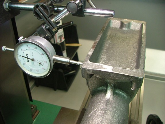
The last step was to check the angle of the casting to the bed travel which was done with the dial indicator as well. I loosened the vise and adjusted till it was as square as possible measuring averages on both sides of the frame.
|
|
|
 |
|
|
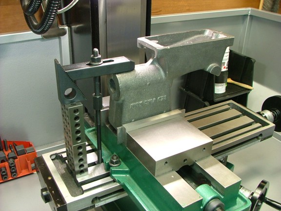
To make sure the frame doesn’t move I clamped down the tail end as seen below. Luckily the frame did not shift after I tightened the clamp so I was ready to go.
|
|
|
 |
|
|
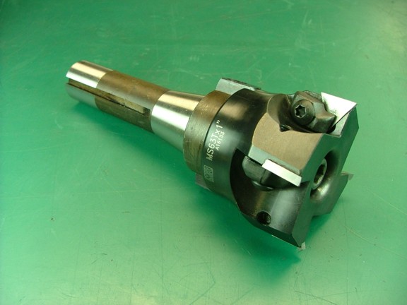
I decided to mill the bottom flat with a 2.5” face mill cutter as seen below. It has indexable carbide tips that are very sharp. This type of cutter makes very clean cuts.
|
|
|
 |
|
|
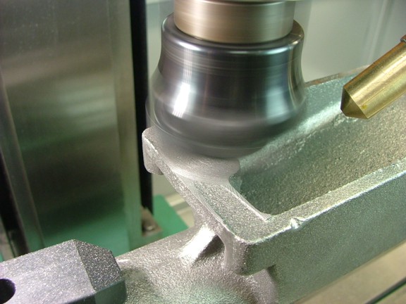
I removed just enough material to square up all edges....
|
|
|
 |
|
|
So far I am really impressed with the rigidity of my new milling machine. My old machine would of probably chattered during this operation.
|
|
|
 |
|
|
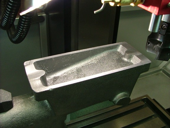
This particular kit comes with the option of an integral fuel tank that can be added to the base of the engine frame. This requires that a pocket be milled into the base to allow a fuel tank bottom to be installed. The manual suggests using a dovetail cutter to machine a lip on the inside of the base so a steel plate can be epoxied into the grove. I am not a big fan of epoxy when it is exposed to liquid fuel for prolonged periods (not to say that this method does not work just fine).
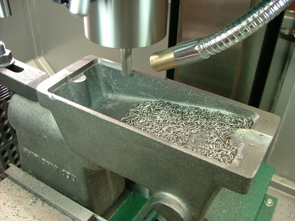
I opted to use a 3/8” end mill to cut a square edged pocket that measures 6.430”L x 2.695”W x .125”D as seen below. This pocket will hold the steel plate as suggested but will be held in place with screws in lieu of epoxy.
|
|
|
 |
|
|
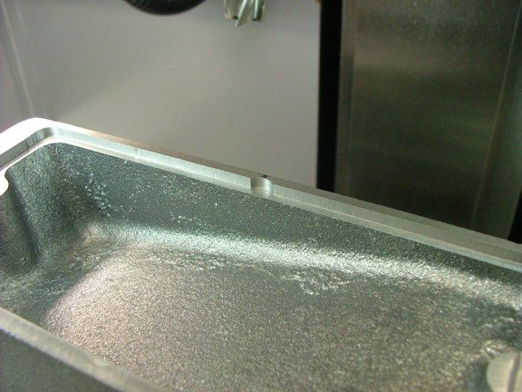
I cut two small additional pockets about .08” deep in the middle of the sides to accommodate the plate screws as seen below.
|
|
|
 |
|
|
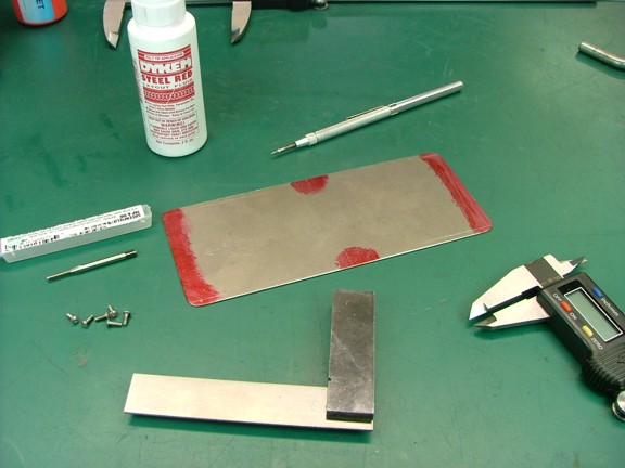
Before I drill and tap the holes I will make the fuel tank bottom out of the .032” thick steel plate provided in the Red Wing materials kit. I layed out the holes in the plate so that the outer four holes were .130” in from the outer edges. The two inner holes of the six will be just inside the edge of the plate and will be cut after the center holes are tapped. I drilled the four outer holes with a #49 drill bit (not shown).
Now before I go any further I think it is worth mentioning that I accidentally spilled 3 ounces of red layout fluid (Dykem) all over my garage floor (not shown). I tipped over the applicator bottle on the floor and the cap snapped off and sprayed fluid all over the shop floor in a ten foot diameter!!! :0( Luckily it spared everything but the concrete but left stains where the floor sealer was cracked which looked hideous.
I used a quart of acetone to clean up what I could but the rough spots on the concrete were bright red :0( Nothing would take the stain out so I was pretty bummed. I decided to try different cleaners and ended up using household bleach as my final try. I was super surprised to see the bleach take out every trace of the red layout fluid as if it had never been spilled.
I now use the 2 ounce felt applicator version of the Dykem (seen below) so that never happens again ;0)
|
|
|
 |
|
|
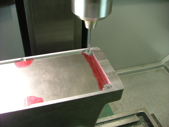
Using the plate as a drill guide I drilled four #49 holes .250” deep on the outer corners.
|
|
|
 |
|
|
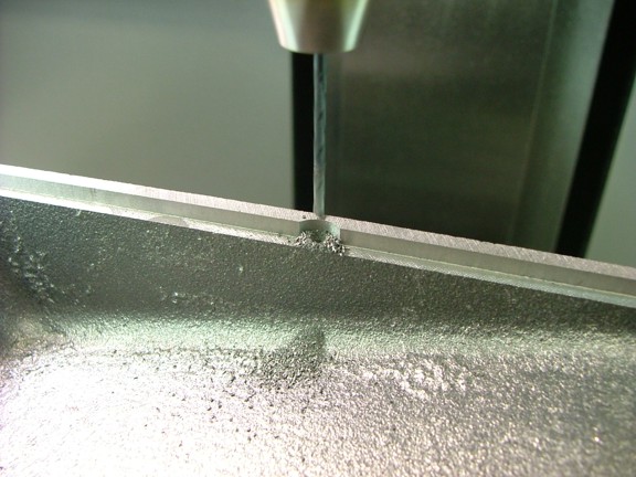
I also drilled the two holes in the middle pockets right on the edge of the plate as seen below.
|
|
|
 |
|
|
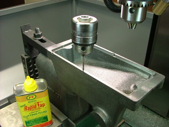
Using an old 3/8” drill chuck as a handle I tapped out the holes with a 2-56 tap. I like to use the drill chuck as it provides more torque control over a “T” handle tap holder. The last thing you want to do is start off with a tiny broken tap in your casting. The cutting fluid is really not necessary in cast iron although I used it in this case to insure success.
|
|
|
 |
|
|
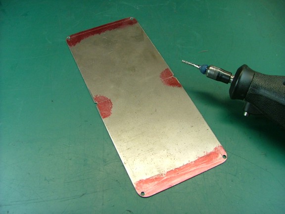
I now cut matching notches in the sides of the plate to accommodate the side screws with the Dremel tool as well as widen the outer holes with a 3/32” drill bit to clear the screws.
|
|
|
 |
|
|
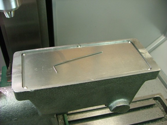
The last step was to test fit the fuel tank plate with a set of 2-56 x .250” screws (not supplied with the kit). The fuel tank bottom will be sealed into place with an aircraft fuel tank sealant later on. This flexible sealant will allow the tank to be opened later on should the tank need servicing. This sealant will also resist cracking like some rigid epoxies can.
|
|
|
 |
|
|
So far so good!!! I look forward to moving ahead with this build so I encourage you to visit again for the continuation of the Red Wing Engine Build!!
Take care my friends!!!
Don R. Giandomenico
|
|
|
 |
|
 |
|