 |
 |
|
 |
|
 |
|
 |
|
 |
|
|
 |
|
 |
|
 |
|
|
|
Posted on October 9, 2012:
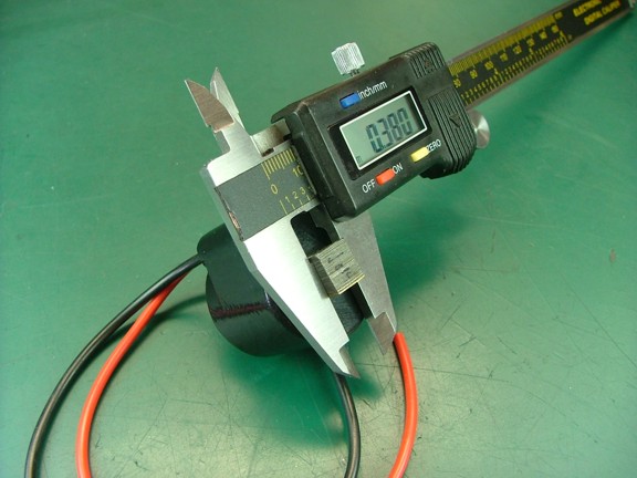
Hello folks! I am continuing work on the Minimag magneto build where I am about to get back to machining the magneto body. At this point I need to mill out the channel where the coil laminations will rest so I measured both sides of the core to determine how wide the channel must be (.380 + .002 clearance)...
|
|
|
 |
|
|
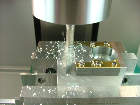
Next I decided to use my reference channel method to accurately mill out the slot for the coil laminations. I used a 5/16 (.3125) end mill to make a .360 deep slot in the center of the required .382 wide channel as seen below. I then zeroed out the table on this cut to be used as a reference point to make the next few cuts. Note: The 5/16 end mill will leave about a .035 gap on either side of the reference channel. I can then fine tune the sides to zero in the proper dimensions.
|
|
|
 |
|
|
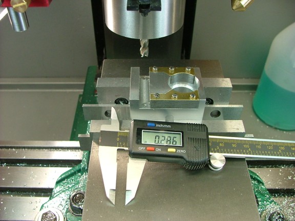
I measured the margin on the top of the body at .286 and then subtracted the required margin of .248 to reveal a cut of .038 (X = -.038). Note: These values are only an example as each reference channel is unique to itself in exact placement each time the method is used.
|
|
|
 |
|
|
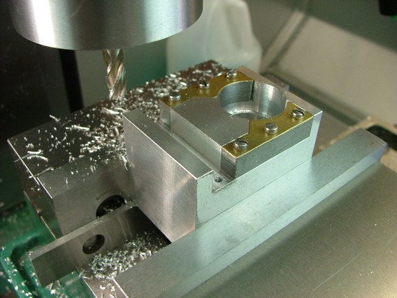
I now moved the table right to .038 and made a pass at .375 deep to complete the top (pictured left) side of the coil channel. I then measured the current width of the channel at .356 and then subtracted that from the required width of .382 to come up with a cut of .026 (X = +.026). I moved the table left to .026 and cut the bottom side of the channel to a depth of .375 to finish the channel.
You will notice that the coil slot slightly encroaches into the field laminations. This is done to flatten up the ends of the field laminations so they will mate correctly with the coil laminations. If the laminations have uneven mating surfaces it can cause a loss of magnetic flux as it is transferred from the rotor to the core of the coil.
|
|
|
 |
|
|
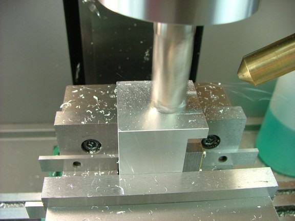
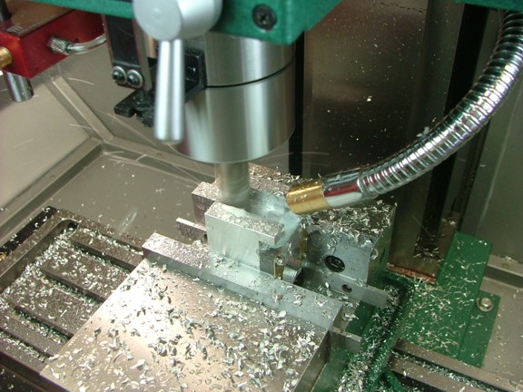
The next step is to start milling out the main recess for the coil itself. I started out by using a 3/4 end mill to make a 1.085 deep slot in the approximate center of the body as seen below. This was done in several passes to keep the end mill from loading up with metal.
|
|
|
 |
|
|
The coolant mister was used once again to help out with the cut...
|
|
|
 |
|
|
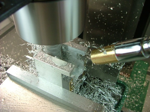
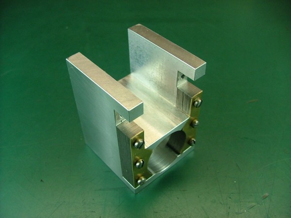
Just as before I used the reference channel method to cut a 1.1 wide x 1.1 deep recess for the coil.
|
|
|
 |
|
|
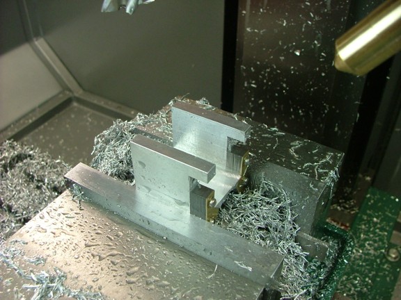
You will notice that the final passes will expose the side of the field laminations (seen below). Be careful not to damage the laminations with the end mill during this process.
|
|
|
 |
|
|
So far so good ;o)
|
|
|
 |
|
|
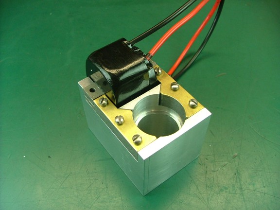
I now tested out the fit of the coil in the channel I made earlier. The .002 added clearance was just enough to allow the coil to fit.
|
|
|
 |
|
|
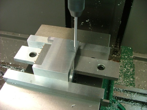
The next step is to profile the sides of the magneto body to form the coil ears. I set up my wiggler tool and located the top right corner of the block and zeroed out the table (not shown). I then moved the table up .991 (X = 0, Y = +.991) for the first cut as seen below.
|
|
|
 |
|
|
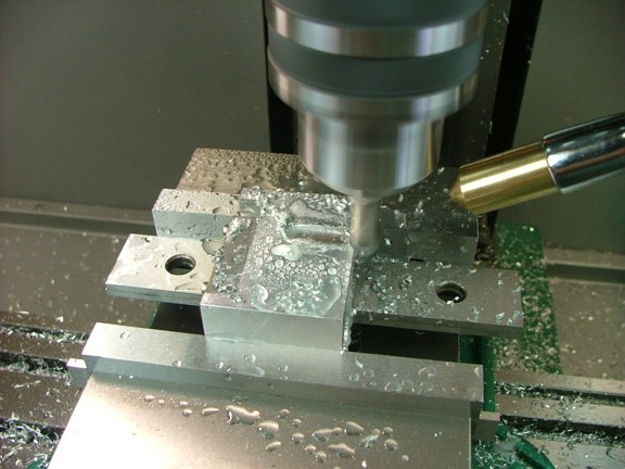
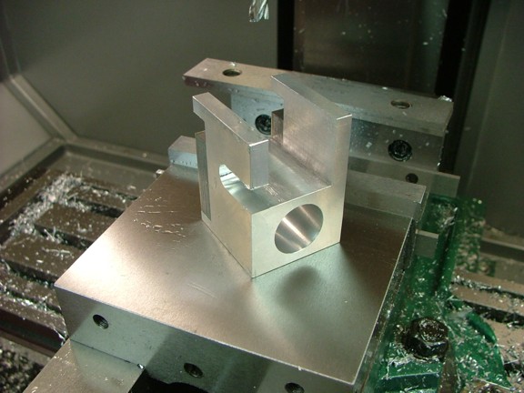
Next I used a 3/8 end mill to cut a slot in the side of the block at a length of .732 from my zero reference (the edge). This slot was located at an offset of .015 from the top surface where the points will mount. This is so that once the rough slot is complete I can make a closer final pass to flush out the intersection of the slot and the flat surface it meets.
|
|
|
 |
|
|
You can see where the slot intersects with the top of the rotor tunnel below...
|
|
|
 |
|
|
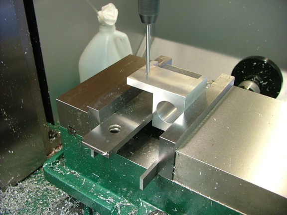
I flipped over the magneto body and duplicated the slot process in reverse. You will notice the use of the parallels as a means of clamping the block in the vise...
|
|
|
 |
|
|
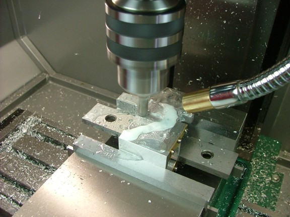
I am finding the coolant mister to be very useful when machining aluminum. The cuts are cleaner and the end mills do not get gummed up with metal. The only hassle is the cleanup which involves making sure all of the Kool Mist fluid is removed from the table and ways once you are done. I always coat the table and ways with way oil or Boeshield before using the mister so that the fluid does not come into direct contact with any bare metal.
Note: Kool Mist cutting fluid is advertised as non corrosive however the water it is mixed with can be so I never leave the coolant on exposed metal overnight...
|
|
|
 |
|
|
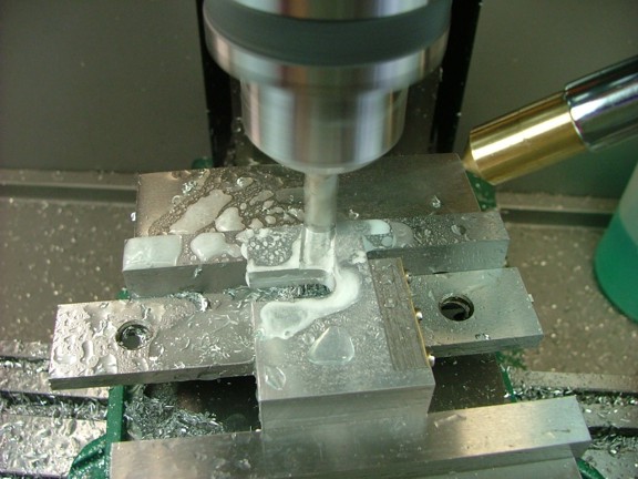
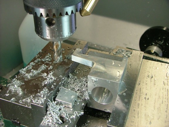
The next step is to finish the profile with an angled cut up from the slots I had made earlier. I angled my milling vise to a 10° angle and trimmed off the corner as seen below. The prints call for a 5° angle however I found that a 10° cut will allow more clearance for the coil wires when it is installed...
|
|
|
 |
|
|
I advanced the table to the left to blend in the radius of the previous cut.
|
|
|
 |
|
|
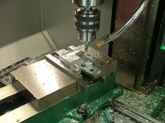
I now repeated the process on the other side...
|
|
|
 |
|
|
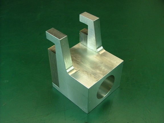
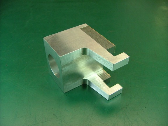
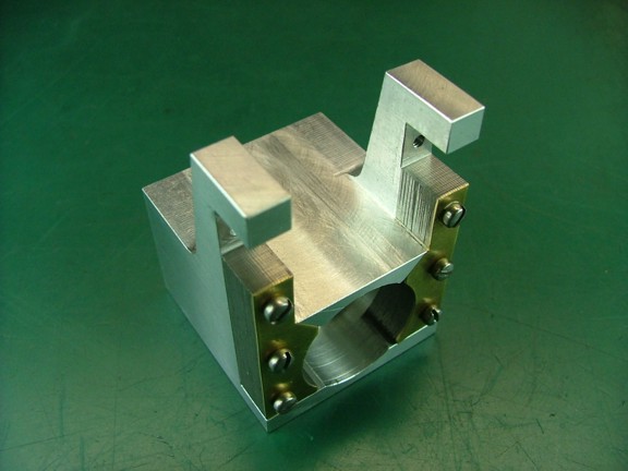
The finished ears really look good at this point :0)
|
|
|
 |
|
|
 |
|
|
 |
|
|
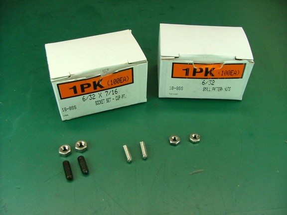
The next step is to drill and tap the holes for the coil ears. The kit is supplied with a set of M4 grub screws and nuts which are used to clamp the coils laminations to the field laminations (below left). I will be substituting this hardware with a set of stainless 6-32 x 7/16 set screws (below middle/right) and pattern nuts (McMatster-Carr Cat# 92311A147, 90730A007). Note: The M4 tap is about $4 more than both boxes of hardware at a 100 count :0P
|
|
|
 |
|
|
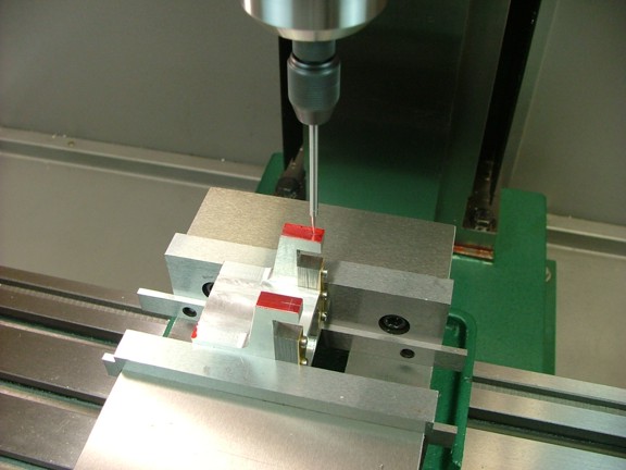
I laid out holes in the coil ears and then centered the spindle up on the first side...
|
|
|
 |
|
|
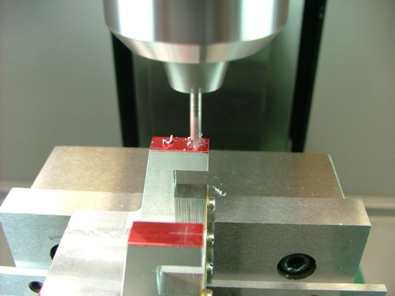
Next I used a #1 center drill to spot the hole...
|
|
|
 |
|
|
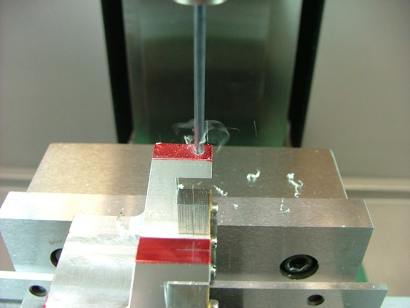
I followed the CD with a #36 drill...
|
|
|
 |
|
|
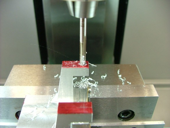
I now used the mill to tap out the 6-32 threads as seen below.
|
|
|
 |
|
|
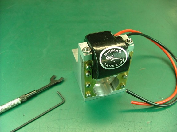
I duplicated the other ear and then installed the coil for a test fit. The clamping screws and nuts worked great.
|
|
|
 |
|
|
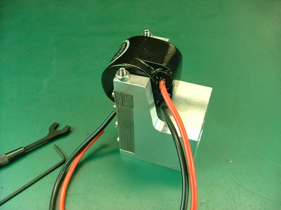
You can see that the red high-tension wire has good clearance from the coil ear. This will help ensure that there will be no tendency for the spark to leap over to the body from where it exits the coil potting.
|
|
|
 |
|
|
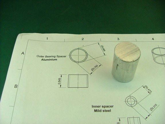
The next step is to make the bearing spacer. This is made out of a piece of 1 aluminum rod that is supplied with the kit.
|
|
|
 |
|
|
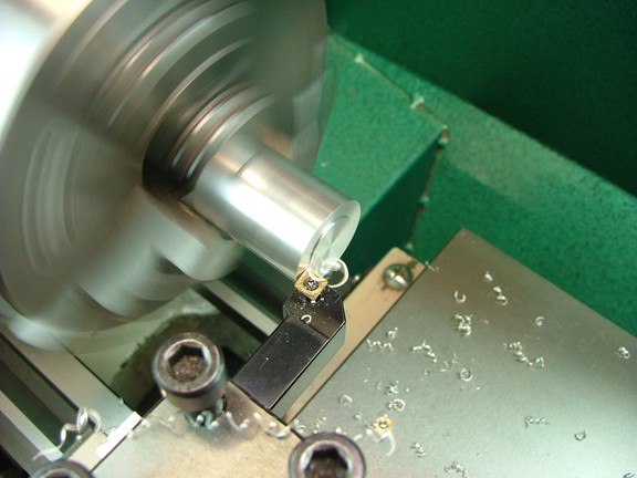
I started out by squaring up one end of the rod in the lathe...
|
|
|
 |
|
|
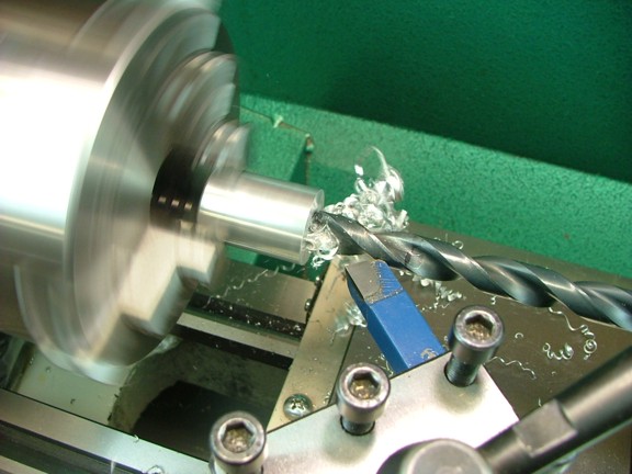
Next I bored a 1/2 hole in one end to a depth of .800.
|
|
|
 |
|
|
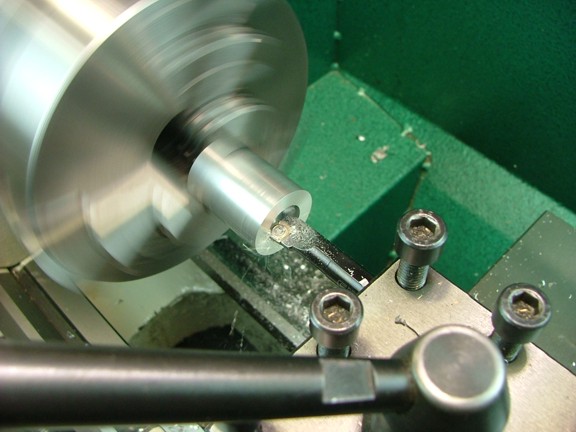
I used my indexable insert boring bar to widen out the hole to an ID of .750.
|
|
|
 |
|
|
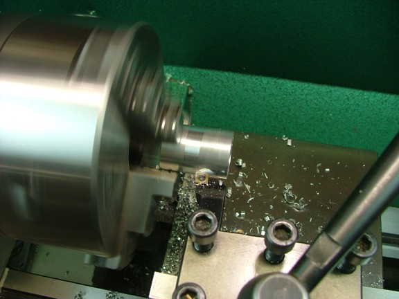
Next I trimmed down the OD to a diameter of .865 which should fit snug into the magneto body.
|
|
|
 |
|
|
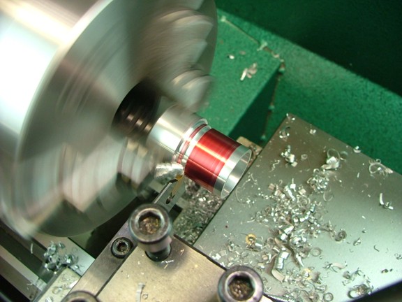
I now parted off the spacer to a length of .660...
|
|
|
 |
|
|
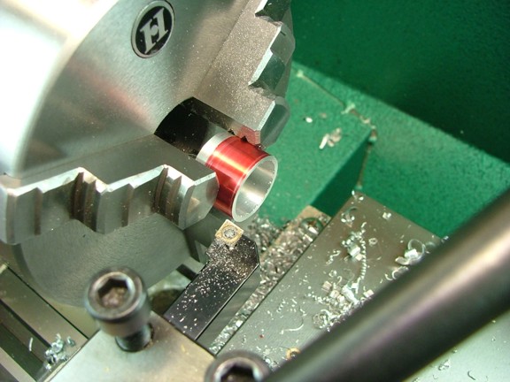
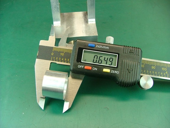
I remounted the spacer into the chuck and then fine tuned the length to .649.
|
|
|
 |
|
|
 |
|
|
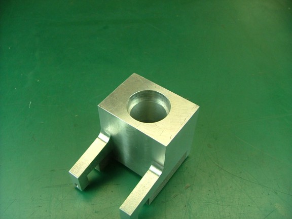
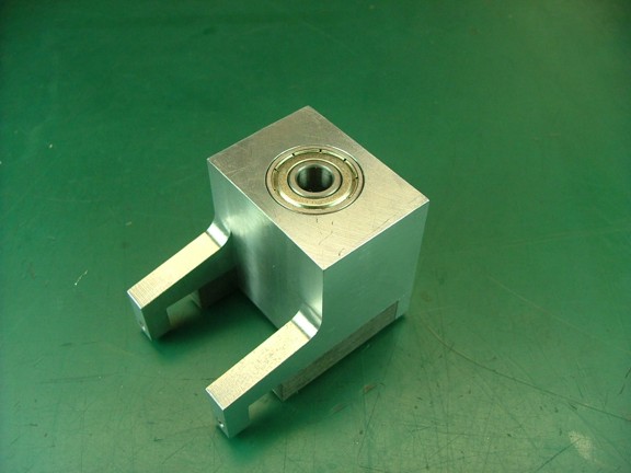
I now deburred the spacer and then drove it into the bore of the body using one of the bearings so that the outer edge of the bearing was flush with the body (about .273 deep).
|
|
|
 |
|
|
 |
|
|
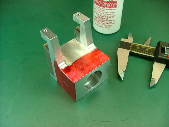
The next step is to lay out the holes for the points cam adjustment and points themselves.
|
|
|
 |
|
|
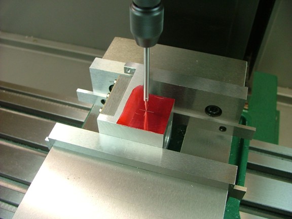
I lined up the spindle on the cam adjustment hole to make the first cut.
|
|
|
 |
|
|
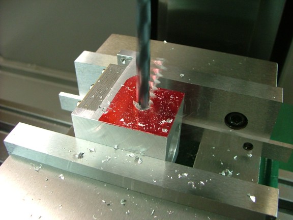
A 16/64 drill bit was now used to drill out the adjustment hole straight through the bearing spacer.
|
|
|
 |
|
|
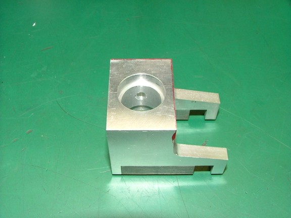
The adjustment hole should be in the center of the spacer as seen below.
|
|
|
 |
|
|
I am making great progress so far and cant wait to see if this magneto will work or not. Please join me again for the continuation of the Red Wing Engine build.
Till then keep machining my friends!!!
Don R. Giandomenico
P.S. I want to thank everyone for their encouraging e-mails. It takes a lot of effort to document these builds and I feel that it is all worth it when I hear that folks are enjoying my articles. Thanks for visiting my site and please come by again. Who knows what I will be getting into next ;0)
|
|
|
 |
|
 |
|
 |
|