 |
 |
 |
|
 |
|
 |
|
 |
 |
|
 |
|
|
|
 |
|
 |
|
 |
|
|
|
Posted on October 6, 2012:
Hello folks. The Red Wing build is very close to completion with the exception of the ignition system and paint. I have spent some time researching what folks have been using for ignition systems and have seen everything from automotive coils to “buzz box” systems. The most popular of which being the buzz box design which the Red Wing kit has drawings for.
I would like my engine to be unique in some way so I have decided to build a miniature magneto to drive the spark plug. This will allow the engine to be run without an ignition battery making it easier to operate. Of course this means more machining and a bit of fabrication although I feel it will really add a nice finishing touch to the engine ;0)
I will be using a magneto kit made by the British Minimag Company that has been successfully used on various model engines. The “Falcon” Engineers Magneto is a compact design that can operate at low RPM which makes it a great choice for the Red Wing engine.
Note: The addition of this magneto “mod” was something that I wanted to try out but may not be desirable to everyone who builds one of these engines. The magneto, although convenient, makes more noise than the traditional “Hit & Miss” fan would like. Most folks like the inherent “swoosh - swoosh - pop” of a hit and miss which is drowned out by the timing gears with this magneto. Using a “buzz box” will produce a longer coast duration between “hits” so careful consideration should be taken before deciding to add a magneto.
|
|
|
 |
|
|
|
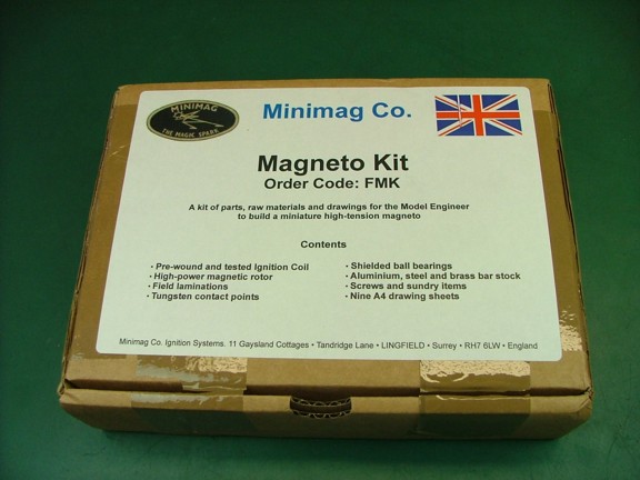
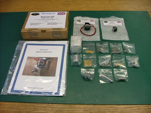
The Falcon magneto kit (Cat# FMK) is supplied with all of the materials and hardware to build a high-tension magneto. A full set of drawings is supplied with the kit as well as a download code to print out an optional 17 page build manual online...
|
|
|
 |
|
|
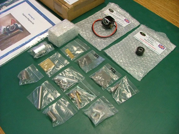
The kit is supplied with metric hardware which is somewhat a hassle if your shop doesn’t have metric taps and dies. I plan to substitute most of the metric hardware to eliminate the need to buy expensive metric tooling.
|
|
|
 |
|
|
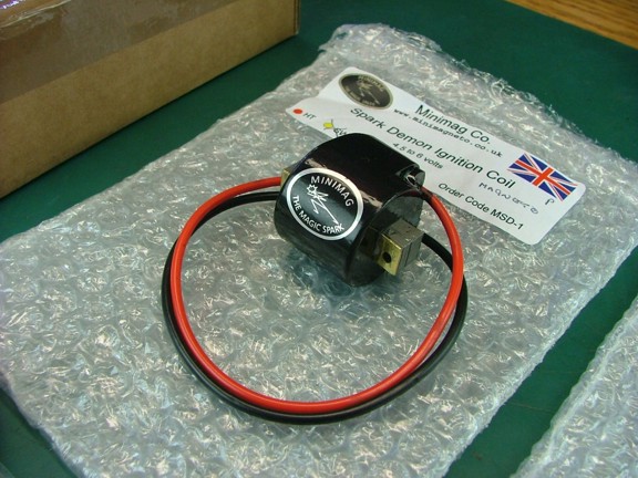
The heart of the Falcon magneto is the Minimag miniature ignition coil. This coil comes finished and tested from the factory as seen below...
|
|
|
 |
|
|
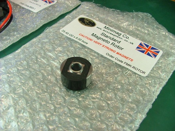
The kit includes a finished rotor with high power neodymium magnets which are used to generate the magnetic field for the coil.
|
|
|
 |
|
|
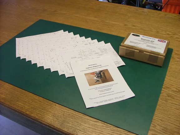
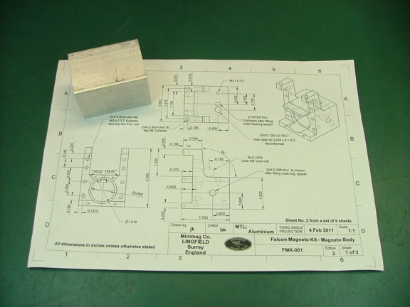
Below are the included drawings which consist of nine pages. I studied all of the prints carefully before proceeding to cut any metal as I do with any kit. I also downloaded the instruction manual (not shown) and studied all of the suggested steps before deciding how I was going to machine the parts.
Note: The instruction manual has a lot of practical advice on how to build the magneto so I will be following it for the most part during this build. I will note any changes to the prints should anyone want to duplicate my setup for their engine...
|
|
|
 |
|
|
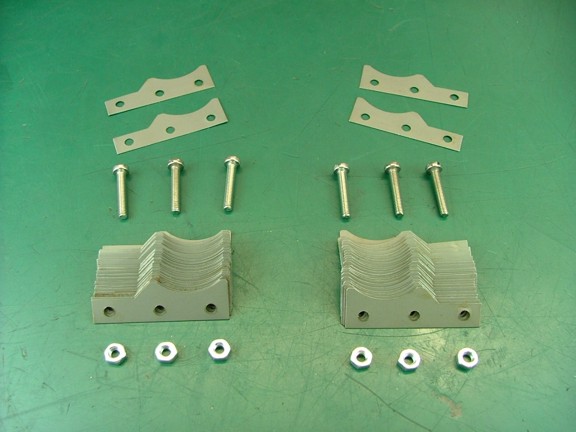
The first step that the manual suggests is to align and glue the field laminations (seen below). I gathered up the provided laminations and hardware from the parts and inspected the laminations for defects...
|
|
|
 |
|
|
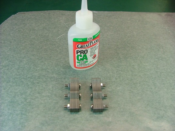
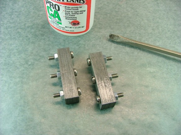
This kit uses 33 steel laminations on each side of the rotor to induce the magnetic field in the core of the coil. The kit comes with 70 laminations (35-left, 35-right) of which I selected the best 66 to stack with each other to make up two 33 piece stacks for the magneto. Once the two stacks were matched I was able to bolt them together using the M3 hardware provided in the kit as seen below. I made sure that there weren’t any gaps in the stacks as they will cause a loss in power.
Note: You will notice that there is a left and right side to assemble. The laminations come in bags that are indicated as such so care must be taken to not mix the pieces together or else the stacks will not fit together flat...
|
|
|
 |
|
|
Once the stacks were aligned and tightened I applied some thin Cyanoacrylate glue to the outside of the stacks to cement the laminations together. This will help the stacks from shifting later on....
|
|
|
 |
|
|
Now that the laminations are glued I can start work on the body of the magneto. The body is made from a 1.75” x 1.75” x 2.4” piece of aluminum that is included in the kit.
|
|
|
 |
|
|
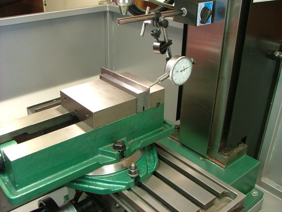
First I aligned my milling vise to the travel of the table using a dial indicator. You will notice that I have my swivel base attached to the vise for future miter cuts.
|
|
|
 |
|
|
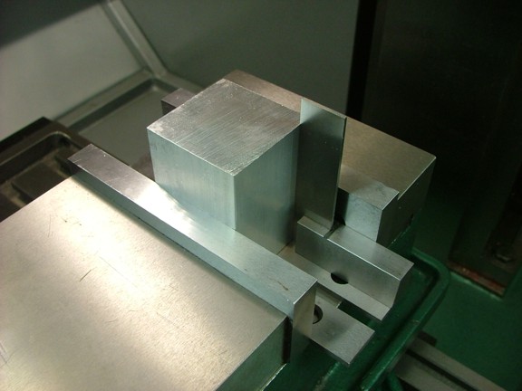
Next I mounted the block in the vise making sure it was vertical to the table.
|
|
|
 |
|
|
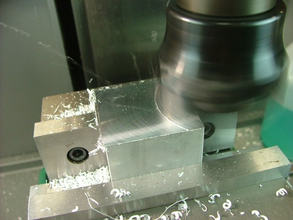
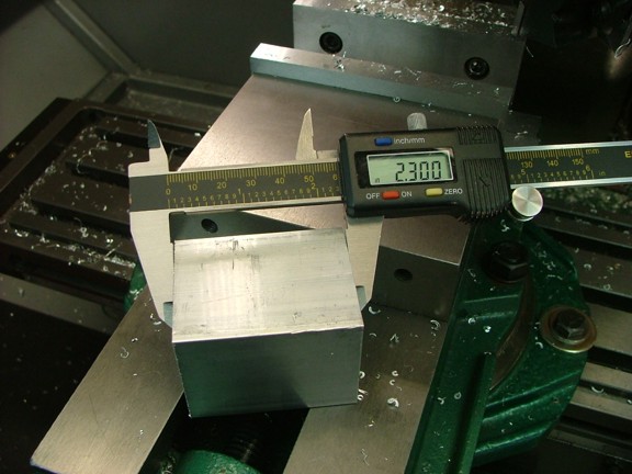
I now used my 2.5” facing tool to square up one end of the block. I then flipped the block over and milled enough material off of the other side to achieve a length of 2.3”...
|
|
|
 |
|
|
 |
|
|
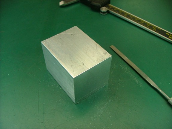
Before moving on I removed the burrs on the edges with a needle file so the block will sit better in the vise.
|
|
|
 |
|
|
Next I placed the block on a set of parallels to prop it up out of the vise and proceeded to face off one side of the block. I then turned over the block and trimmed it down to a width of 1.7” (not shown).
|
|
|
 |
|
|
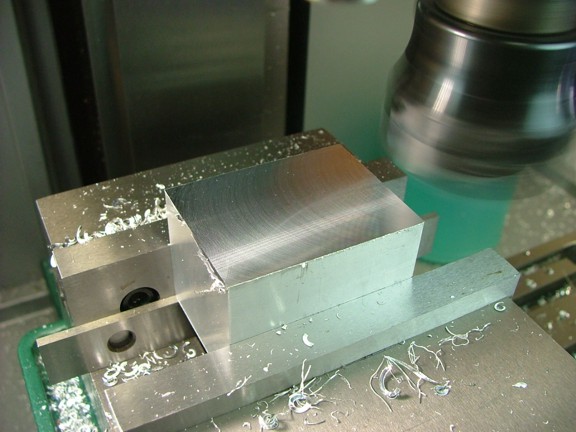
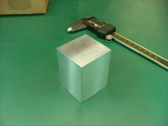
I turned the block 90° in the vise and milled the other sides to a width of 1.65” to complete the overall dimensions of the body. I then checked the block with my calipers to ensure that all of the sides were parallel to each other.
|
|
|
 |
|
|
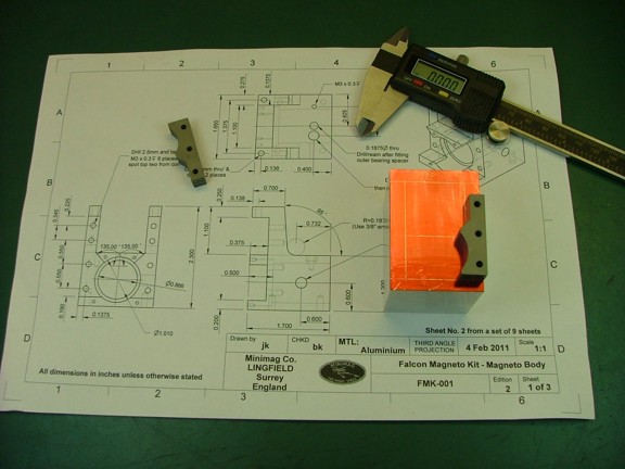
The next step is to lay out the cut lines for the lamination stacks. These lines will be used as a visual reference although the actual dimensions will be referenced off of the outer sides of the block as machining progresses.
|
|
|
 |
|
|
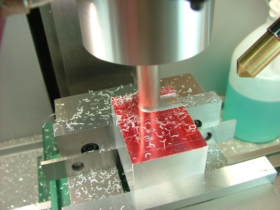
I now set up the block in the milling vise so that the 1.65” wide face was positioned up and cut a .360” deep x 9/16” wide “reference channel” at .592” down from the back edge of the block (to center of spindle). This channel will serve as a gauge to determine the “actual” cutting width of the 9/16” end mill as well as the “actual” position of the spindle over the workpiece. I zeroed out the “Y” axis on this cut before moving on to the next step.
Note: The actual “top” of the magneto body is positioned towards the operator at this point. You can see that I scribed “top” on the block in the picture below...
|
|
|
 |
|
|
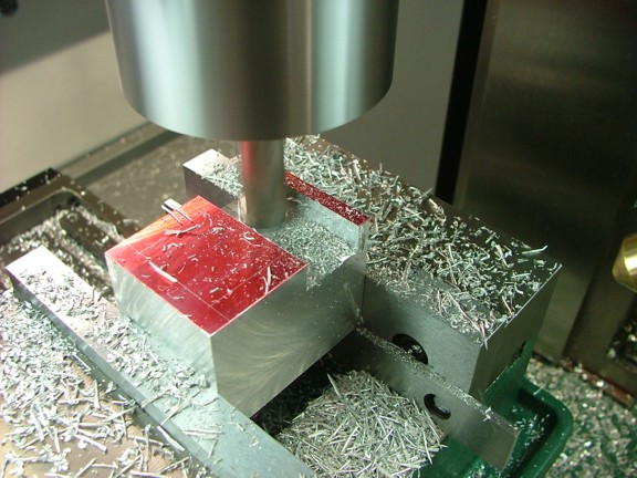
Next I measured from the back edge of the block to the back edge of the newly cut channel with my calipers to determine how much more material will need to be removed to achieve a margin of .200” at the “bottom” of the block. I measured .313” so the table will need to move down -.113” for the next cut to make the slot’s margin at .200” from the back edge of the block.
I moved the table down to -.113” (up from my zero reference) and made a pass at a finished depth of .375”. I then measured the new width of the channel (.672”) to determine how far down I will need to cut to make the channel .800” wide as the prints require. I deducted my existing width of .672” from the desired width of .800” and came up with .128” which is where I moved the table to (Y = +.128” from the zero reference). Finally I cut the front side of the channel at a depth of .375” to finish off the job.
Note: Whenever I use my “reference channel” method I always make my first cut at .015” above the final depth of the channel. Example: .360” instead of .375”. This is done to allow the finished surface to be made by the final passes of the end mill which will reduce tool deflection and thus increase accuracy.
|
|
|
 |
|
|
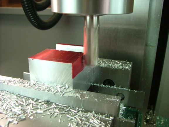
The next step is to mill out two recesses for the field laminations on the sides of the block. I installed a 5/16” end mill in a collet and then used it as an edge finder to zero out the “X” axis on the side of the block as seen below. I turned on the spindle and moved the table into the end mill until the layout fluid showed contact. I then zeroed out the X axis so that my cuts will be accurate to the table’s graduated dials.
Note: Whenever I need to mill out a deep slot or remove a lot of material I make several progressive passes instead of one. This will reduce side force on the spindle and thus increase accuracy. The end mill will run cooler as well as eject material more efficiently...
|
|
|
 |
|
|
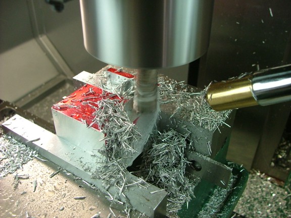
I started to cut the right recess for the lamination stack at a width of .275” starting up at about .300” from the front edge of the block (X = -.275). This was done at a depth of .375” which should match the depth of the channel made earlier. Note: I used my coolant mister for these slots as the metal started to gum up in my tooling.
|
|
|
 |
|
|
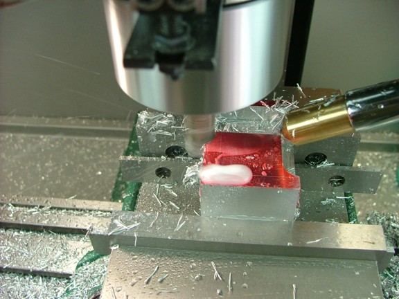
I now proceeded to cut the left side using the same method as before.
|
|
|
 |
|
|
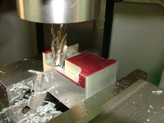
You will notice that I stopped the cut at .300” up from the front edge (seen below).
|
|
|
 |
|
|
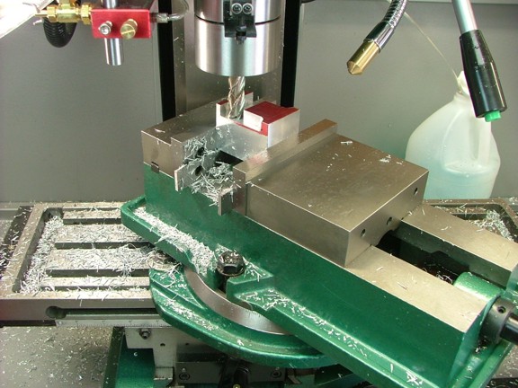
I now repositioned the vise so that it was 45° to the milling table using the swivel base. This is in preparation for milling out the angle cuts for the field laminations.
|
|
|
 |
|
|
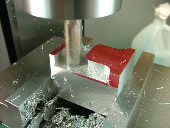
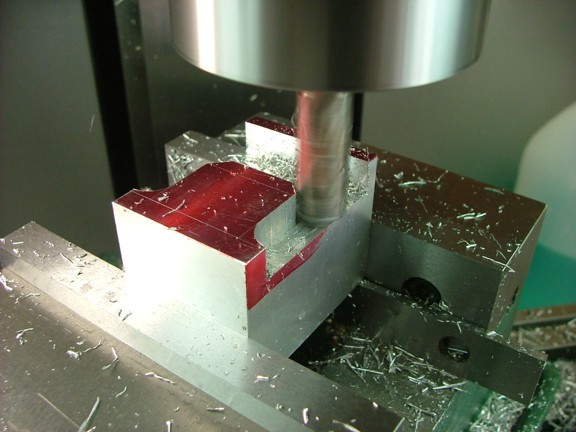
I had scribed a line at 1.086” from the “top” of the body across the face of the block as a cutting guide. This line serves as a stopping point for the 45° angle cuts as seen below.
|
|
|
 |
|
|
 |
|
|
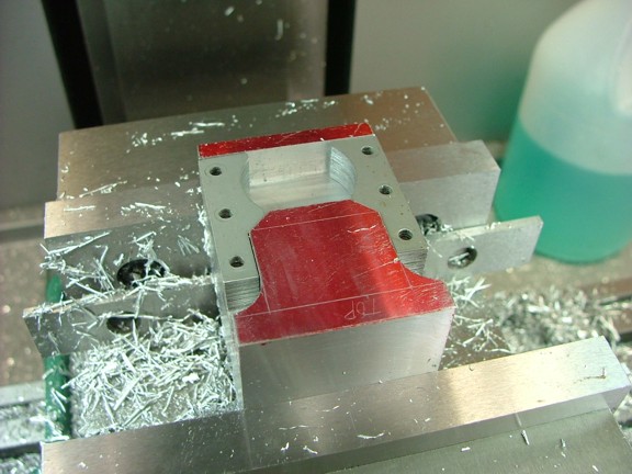
I now tested the fit of the field laminations on the block at this point making sure that they both fit flush in their recesses...
|
|
|
 |
|
|
The next step is to lay out the center of the rotor bore at .600” up from the bottom of the block (centered).
|
|
|
 |
|
|
I now lined up the spindle on the center mark with the wiggler tool...
|
|
|
 |
|
|
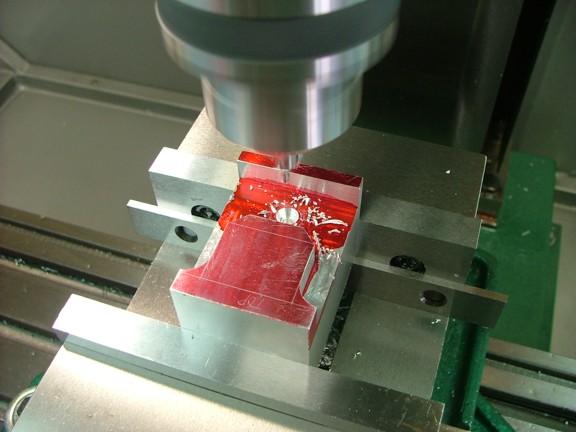
I used a #4 center drill to spot the rotor bore center to almost the full depth of the bit’s taper. This will make it easier to center the block on the lathe’s 4-jaw chuck with a test indicator.
|
|
|
 |
|
|
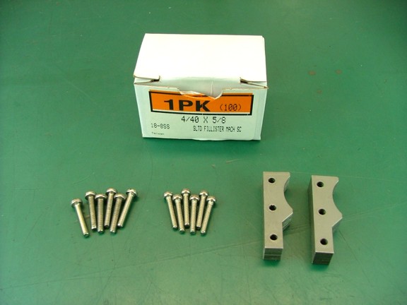
I had mentioned earlier that I was planning to substitute some of the hardware with SAE fasteners as to avoid me having to buy expensive metric taps and such. The first of these substitutes will be the lamination screws which originally were M3 x 16 mm (below left). I chose to sub them with 4-40 x 5/8” stainless screws (McMaster-Carr Cat# 91794A112) as seen below (middle).
Note: The M3 tap needed for the kit’s hardware is about $4 more than a hundred 4-40 screws as well as three times as expensive as a standard 4-40 tap :0P
|
|
|
 |
|
|
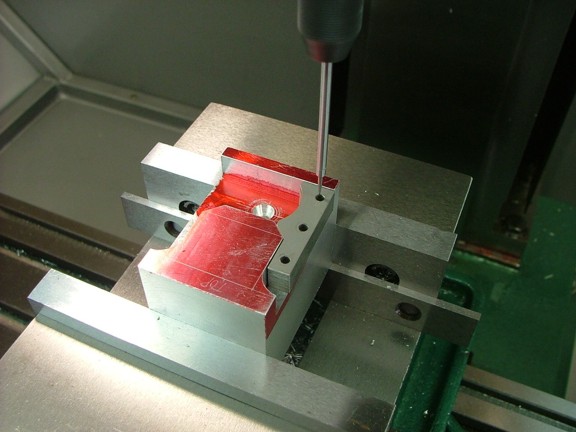
I now mounted the block back into the milling vise and laid the laminations in their recesses so that the spindle could be aligned with the lamination holes.
|
|
|
 |
|
|
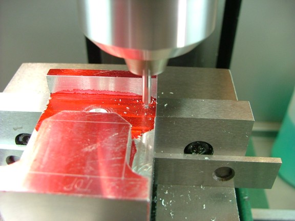
Each hole location was spotted with a center drill as seen below.
|
|
|
 |
|
|
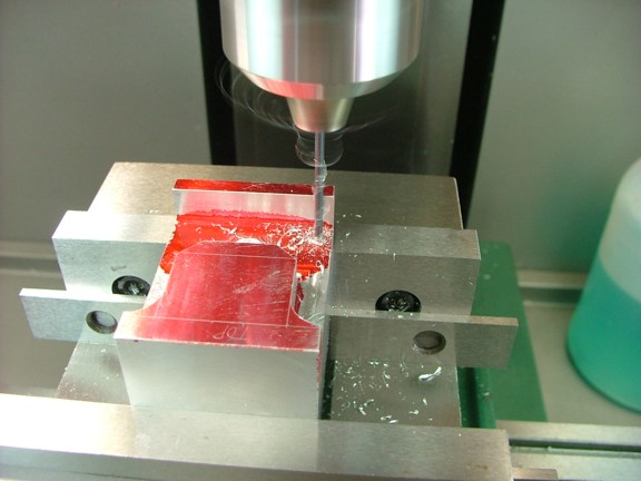
Next I drilled each location with a #43 drill to a depth of .3”.
|
|
|
 |
|
|
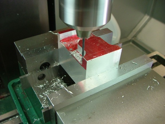
I laid out the top two holes for the coil core per the drawings and drilled them at this time as well...
|
|
|
 |
|
|
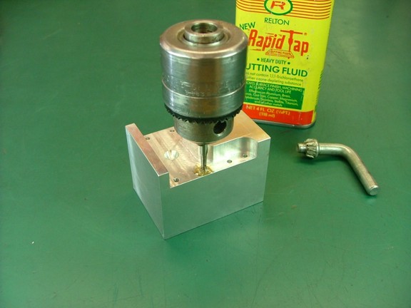
I now tapped each hole using a 4-40 hand tap...
|
|
|
 |
|
|
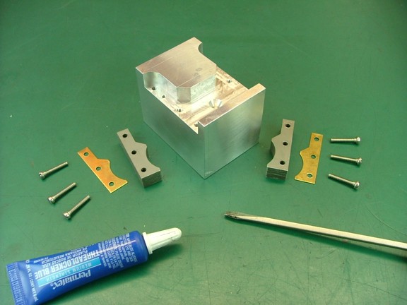
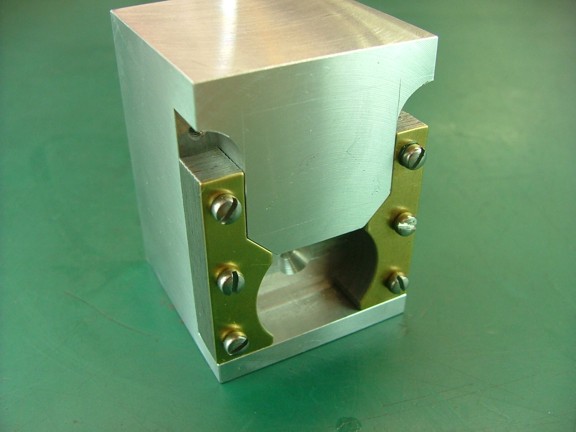
I am now ready to permanently mount the field laminations to the body. I gathered up the brass cap plates supplied with the kit and fastened the assemblies down to the block. Note: I applied some blue Locktite to the screws as well as the mating surfaces so the laminations will not shift later on...
|
|
|
 |
|
|
 |
|
|
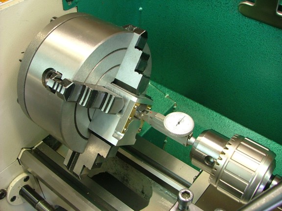
I now moved the block over to the lathe and mounted it in a 4-jaw chuck as seen below. I used a test indicator to center the rotor bore in the chuck which must be perfect before drilling the rotor bore. Note : I used some aluminum sheeting to protect the block from the jaws of the chuck.
|
|
|
 |
|
|
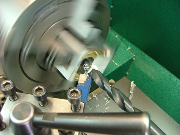
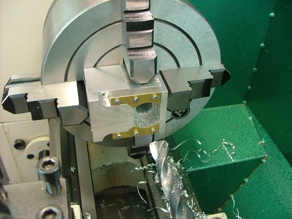
I proceeded to use a 1/2” drill bit to bore a hole straight through the block as seen below...
|
|
|
 |
|
|
 |
|
|
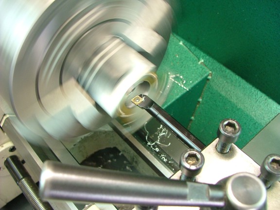
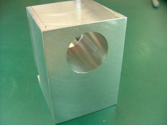
The next step is to use a sharp boring bar to bore out the block straight through to an ID of .864”. Note: I found that “dragging” the bit backwards (to the right) made for a better finish on the final passes...
|
|
|
 |
|
|
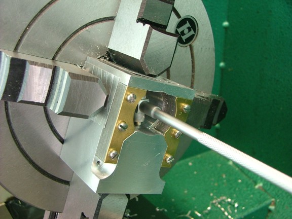
I checked the bore with a telescopic gauge and micrometer to confirm the correct diameter at both ends of the bore before moving on.
|
|
|
 |
|
|
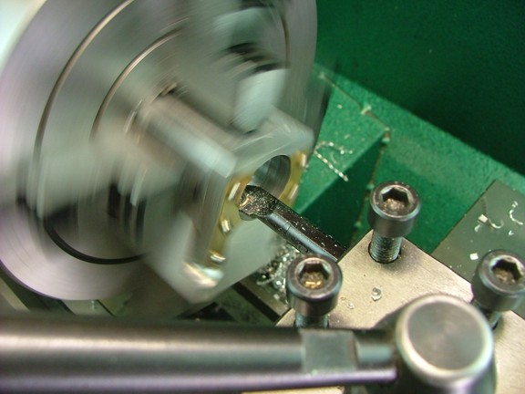
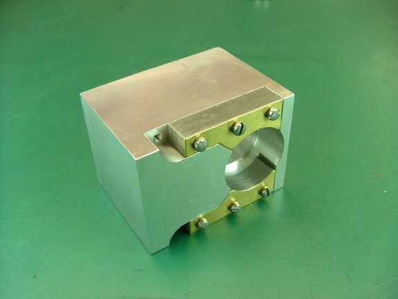
The next step is to bore out the pocket for the magnetic rotor to a diameter of 1.010” which leaves .005” side clearance for the 1” rotor. Of course each rotor supplied with every kit should be measured to ensure that there is no more than .010” side clearance from the laminations or else the magneto may not work well at low RPM.
Note: The rotor pocket should slightly encroach into the field laminations so expect to cut some of the steel off of the stacks when boring the pocket.
|
|
|
 |
|
|
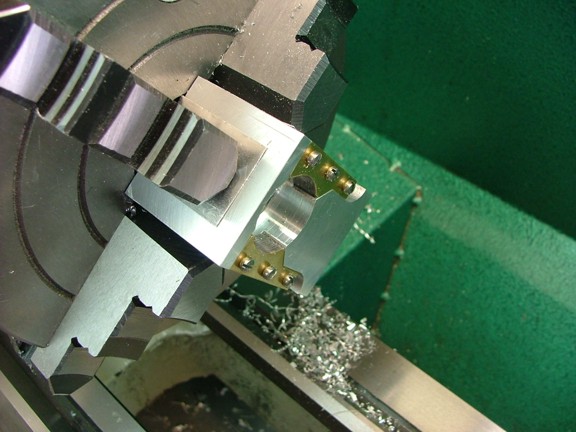
I bored the pocket to a depth of .530” for added clearance however the prints call for .500”.
|
|
|
 |
|
|
So far so good ;0)
|
|
|
 |
|
|
 |
|
|
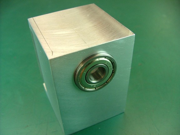
I tested the fit of the provided 22 mm OD bearings in the rotor bore and verified a snug fit on both ends. Note: A press fit is not ideal as you may want to service the points cam (between the rotor bearings) later on...
|
|
|
 |
|
|
This magneto kit is proving to be really fun to machine. I can’t wait to see if this thing will actually work on my engine ;0)
Please join me again for the continuation of the Red Wing Engine Project next week!!
Till then be safe my friends!!!
Don R. Giandomenico
|
|
|
 |
|
 |
|
 |
|