 |
|
|
|
|
|
|
|
|
|
|
 |
|
|
|
 |
|
 |
|
 |
|
|
|
Posted on October 21, 2012:
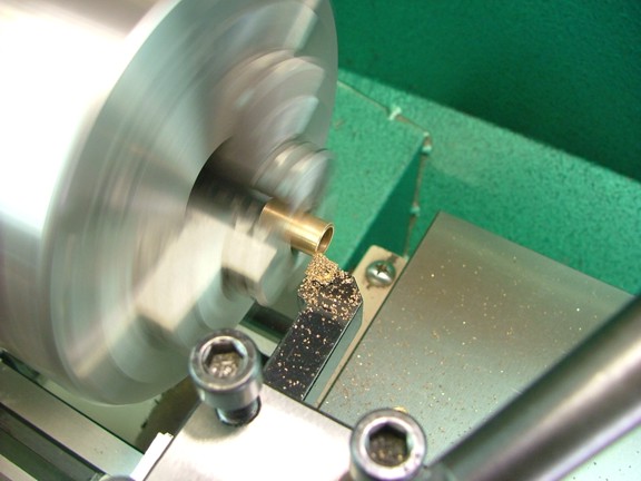
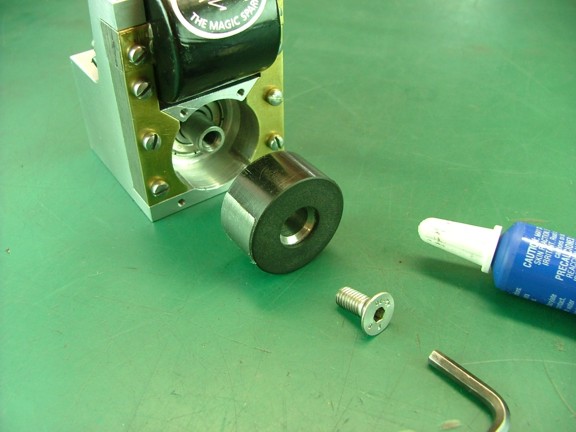
Hello again folks!!! I am down to the wire my friends so I couldnt be more excited to finish. The next step is to prepare the bronze bushing for the idler gear. I ordered this oil-lite bushing from McMaster-Carr (Cat# 6391K155) which has an ID of 5/16 and an OD of 3/8. The bushing comes at 3/4 long so it must be trimmed down to .648 to fit onto the idler gear shaft I made earlier.
|
|
|
 |
|
|
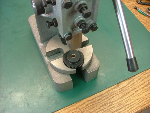
Luckily the stock timing gear already has a 3/8 bore so the bushing will simply press into the hole as seen below. If the bushing is slightly too small you can use blue Locktite to secure it into the gears bore...
|
|
|
 |
|
|
And now for a fit check. You should be able to tighten the 1/4-20 nut on the end of the shaft without hitting the bushing. If the gear does not spin freely you can trim down the bushing a bit more.
|
|
|
 |
|
|
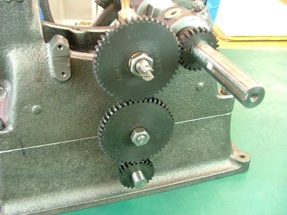
I put the rest of the gears together to see if the setup will work or not and was happy to see that the shaft spacing looks good. Unfortunately there will be some lash in the gears which is unavoidable with this type of gear...
|
|
|
 |
|
|
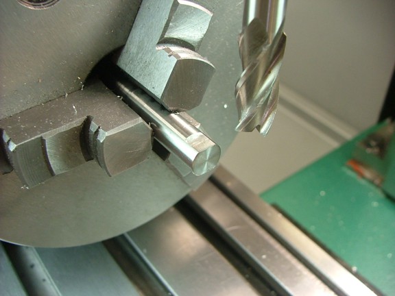
The next step is to prepare the magneto shaft. I removed the shaft from the magneto assembly and trimmed the big end down by .100 for a total shaft length of 2.9 (not shown). I then mounted the shaft in the rotary table to cut a set of flats on the end at .030 deep by .230 wide as seen below. These flats will allow a 5/16 open end wrench to be used to adjust the ignition timing later on...
|
|
|
 |
|
|
 |
|
|
Next I reinstalled the shaft back into the magneto assembly and used some blue Locktite to secure the rotor screw as seen below. Because I had disturbed the alignment of the points cam I will need to set the magnetic timing once again...
|
|
|
 |
|
|
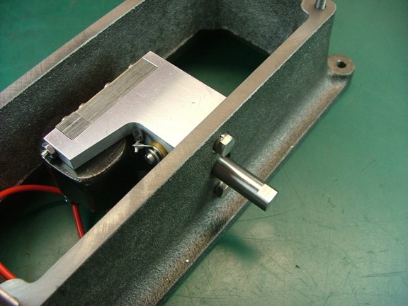
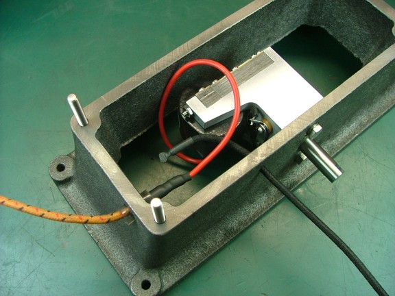
I moved the magneto over to the lathe and aligned the magnetic timing as I had before (not shown). I then mounted the magneto in the engines base as seen below.
|
|
|
 |
|
|
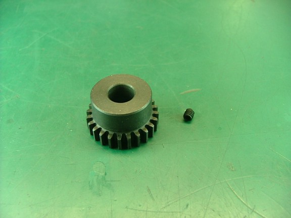
The next step is to drill and tap the hole for the magneto gear set screw...
|
|
|
 |
|
|
I set the gear in my milling vise and centered up the spindle over the hub of the gear using my round stock center finder (not shown). I then spotted and drilled a #29 hole into the hub. I then tapped the hole with an 8-32 tap as seen below.
|
|
|
 |
|
|
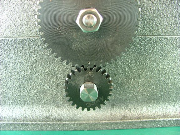
The next step is to mark the new timing gears so that they line up with the existing marks on the engines gears. I rotated the engine so that the existing 48 tooth gears center punch mark was facing downward (not shown). I then marked the idler gear with a center punch directly below the timing gear mark to indicate the correct orientation of the two gears. I then rotated the gears until the mark traveled to the bottom of the idler gear where I made a mark on the magneto gear to indicate proper alignment (shown below). The timing gears can now be easily aligned during assembly.
Note: I had the chance at this point to see how the gears would react to the magneto while turning the crank. Unfortunately as I suspected the magneto makes the gears chatter :0/ The noise is to be expected although I am not sure if it will quiet up when the engine is running or not. At this point I am not going to worry about the noise however I will have to start thinking about a solution should the chatter be excessive when the engine is running.
|
|
|
 |
|
|
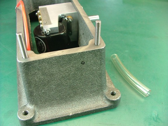
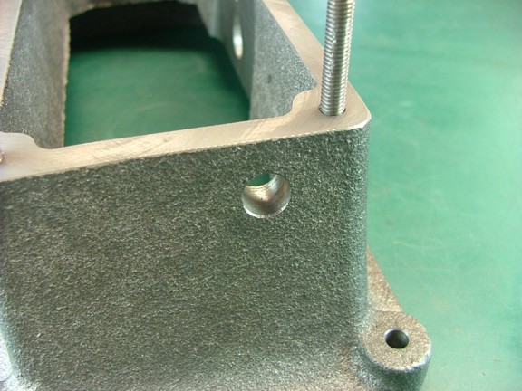
The next step is to drill a hole for the high-tension wire to exit the base. I laid out a hole at .460 down and .850 to the left of the bases side as seen below.
|
|
|
 |
|
|
Next I drilled a 11/32 hole at this location...
|
|
|
 |
|
|
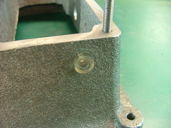
I now used a piece of vinyl 1/4 ID tubing to make an insulated throat for the hole as seen below. The tubing will help prevent the spark from leaping from the HT wire as it exits the base...
|
|
|
 |
|
|
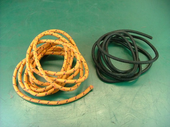
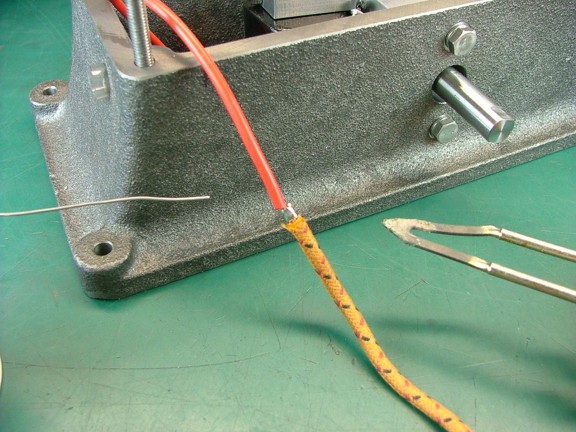
The next step is to install a piece of cloth covered wire on the HT lead to give more of a scale look over the red HT lead. I purchased 3 of orange and 3 of black fabric covered wire for this purpose (Cat# Wire-014 - Wire-B16). I will use the orange wire for the HT lead and the black wire will be used as a dummy lead from the engines timing lever.
Note: The copper points I built for the engine wont be used on this project although they add some scale appeal to the engine. I decided to add a dummy wire to the timing lever contact to give the appearance that the points are being used...
|
|
|
 |
|
|
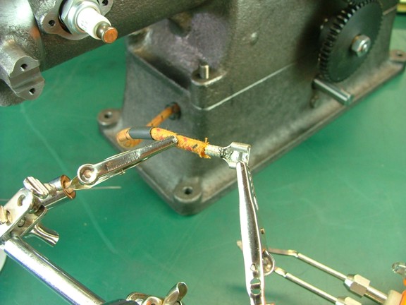
I soldered on a piece of orange wire to the existing HT lead as seen below.
|
|
|
 |
|
|
Next I used some heat shrink tubing to seal the solder joint. I used two layers of tubing which covered the joint about a 1/2 on either side of the joint.
|
|
|
 |
|
|
The next step is to make a connector for the spark plug. This is a pretty easy task as all you need is a 1/4 quick-disconnect terminal (below left) of which you can file off a little on the end so it will fit evenly on the CM-6 spark plug tip (below right).
|
|
|
 |
|
|
Next I cut the orange wire down to 6 long and then soldered on the new spark plug connector. I then used a piece of heat shrink tubing to finish off the job...
|
|
|
 |
|
|
 |
|
|
The next step is to drill a hole for the dummy wire for the points. I drilled a #28 size hole at .460 down and 1.350 to the left of the magneto holes center for the dummy wire.
|
|
|
 |
|
|
Next I used a piece of heat shrink tubing to seal off the end of the wire so it cannot inadvertently touch the points on the magneto.
|
|
|
 |
|
|
Now I needed a way to connect the dummy wire to the points on the engine so I found a small ring terminal to use for the connection...
|
|
|
 |
|
|
I soldered on the ring terminal followed by some heat shrink tubing...
|
|
|
 |
|
|
Since the copper points will not be used on the ignition system I decided to remove the provided spring (below left) and replace it with a smaller spring (below right) so that there is less pressure on the contact. This will prevent the contact from wearing unnecessarily.
|
|
|
 |
|
|
Lastly I mounted the dummy wire on the timing lever contact as seen below.
|
|
|
 |
|
|
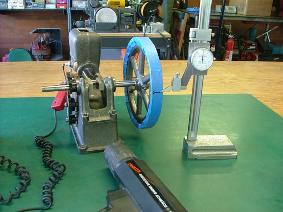
Now that the ignition system is all bolted together I can set the ignition timing to the crank position. I installed a spark plug into the engine so the magneto could fire the plug and then hooked up my automotive timing light to see what degree the plug was firing at on the crank. I then marked the flywheel with 0° reference mark (lined up with my height gauge) so as I could tell where the crank was at Top Dead Center (TDC). I then spun up the flywheel by hand to dial in the spark timing so that the timing light lined up the 0° mark with my height gauge.
Once the ignition timing was set to 0° (TDC) I made a reference mark on the magneto shaft and timing gear so 0° could be set mechanically from these marks (not shown).
|
|
|
 |
|
|
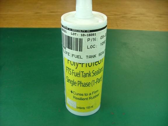
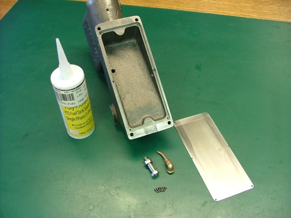
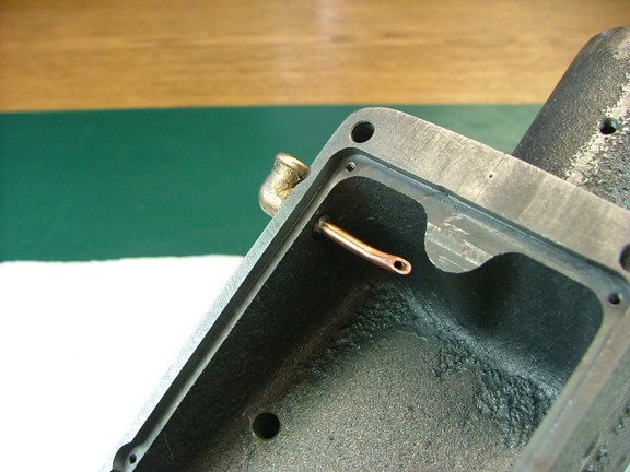
The next step is to seal the fuel tank plate and fittings into place using an aircraft fuel tank sealant. For this I purchased some Aerolife Poly-ProTech FTS fuel tank sealer from Aircraft Spruce (Cat# 09-02544). This sealant is fuel proof and stays flexible so it wont crack free from the fuel tank plate. The best part about using this sealer is that it can be removed and reapplied later on should the fuel tank need servicing inside.
|
|
|
 |
|
|
I prepared the engine frame by cleaning it with Brakleen parts cleaner as well as the fuel tank plate and fittings (not shown). This will remove any oils left over from the machining process so as to allow the sealant to stick to the parts. Note: This is an important step or else you may have a leaky tank :oP
|
|
|
 |
|
|
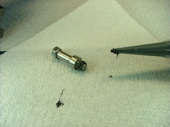
I first applied some of the Aerolife sealant to the idler gear shaft.
|
|
|
 |
|
|
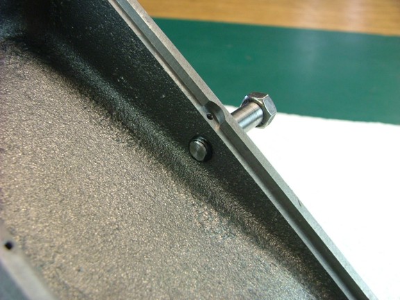
I now installed the shaft into the frame as seen below.
|
|
|
 |
|
|
After I tightened the shaft into place I removed the excess sealant on the outside of the frame with acetone on a rag (not shown).
|
|
|
 |
|
|
Next I installed the fuel sump fitting using some sealant on the threads...
|
|
|
 |
|
|
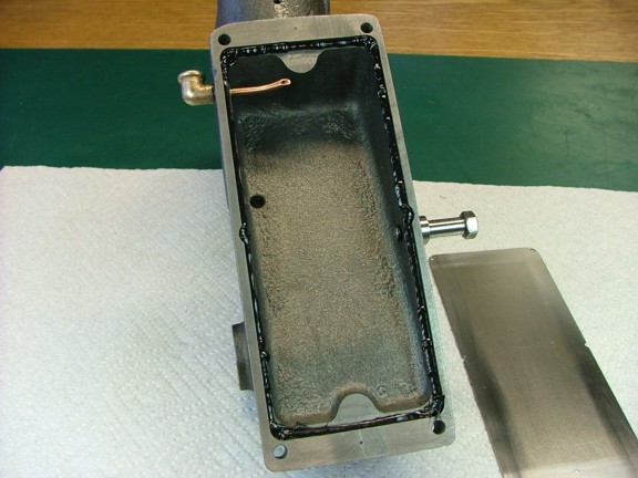
I applied a bead of sealant along the bottom of the tank plate recess as seen below...
|
|
|
 |
|
|
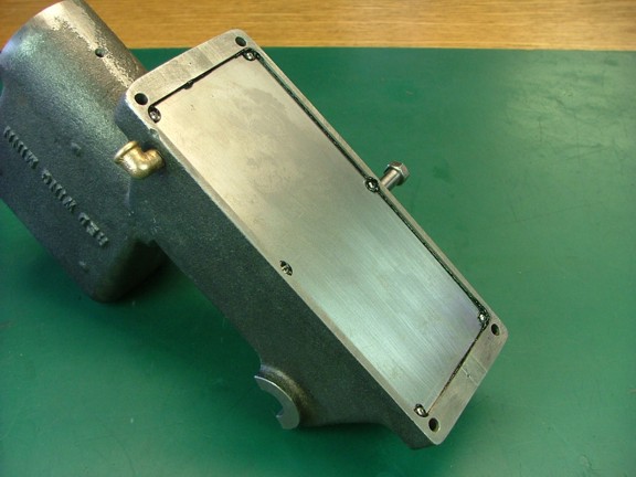
I now fastened the tank plate in place using the six 2-56 tank screws. I then put the engine frame away to cure for 48 hours before disturbing the assembly. Note: The Aerolife tank sealant requires at least 72 hours of cure time before submerging it in fuel...
|
|
|
 |
|
|
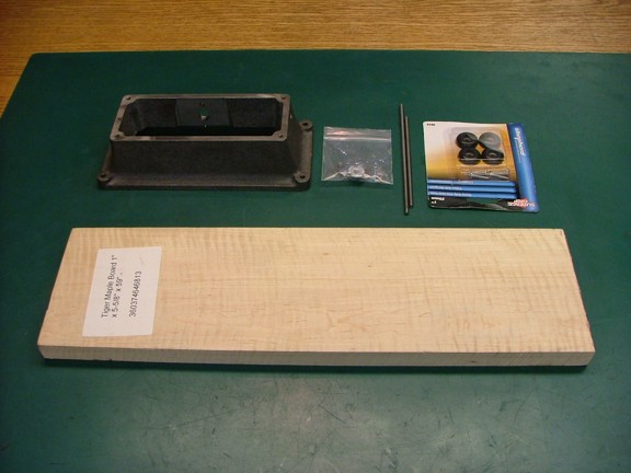
The next project to tackle is to make the wooden skids for the engine. The skids were used on the full scale engines to help the operator move the engine from one place to the next. The skids also served as a way to keep the engine up and off of the dirt. Fancy engines offered an optional wheeled cart but most farmers didnt have the extra $2 to afford this luxury :0P
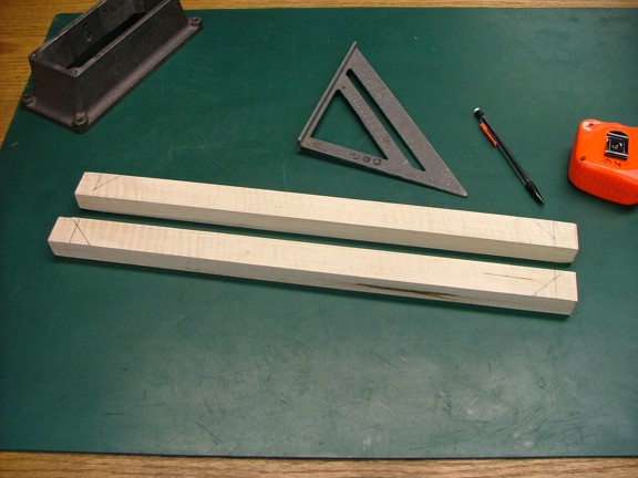
I will be making my skids out of hard tiger maple of which I got a piece from eBay a few months back (seen below). Maple is a really nice wood to make skids from although you must properly seal the wood or else engine oil and grease will stain the light colored wood.
|
|
|
 |
|
|
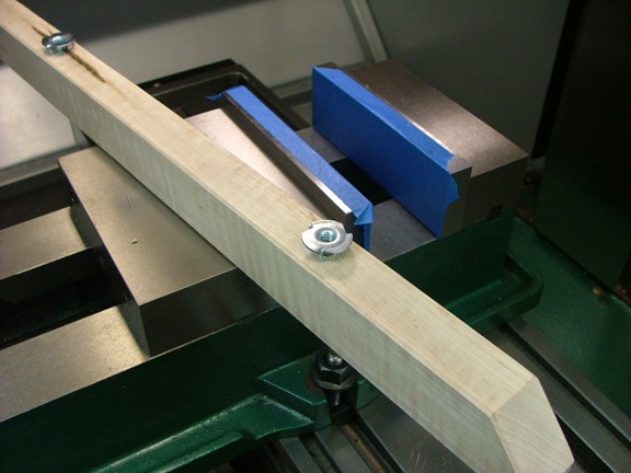
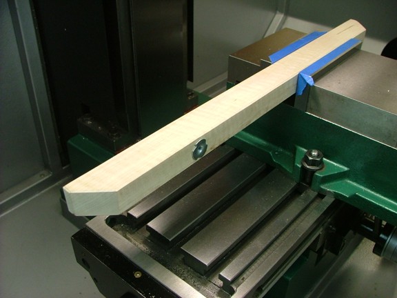
I started out by cutting two pieces of the maple to 1-1/4 x 7/8 x 19. I then laid out cut lines at 17.5 apart from each other on each skid with 45° angle cuts that intersect the ends leaving a 3/8 tall flat spot at each end.
|
|
|
 |
|
|
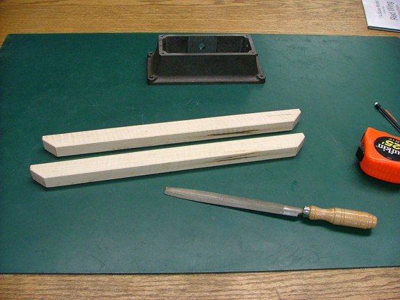
Next I trimmed the skids at the cut lines and then used a wood file to contour all of the corners of the skids. Note: I was very careful to not get dirt or oil on the wood at this point.
|
|
|
 |
|
|
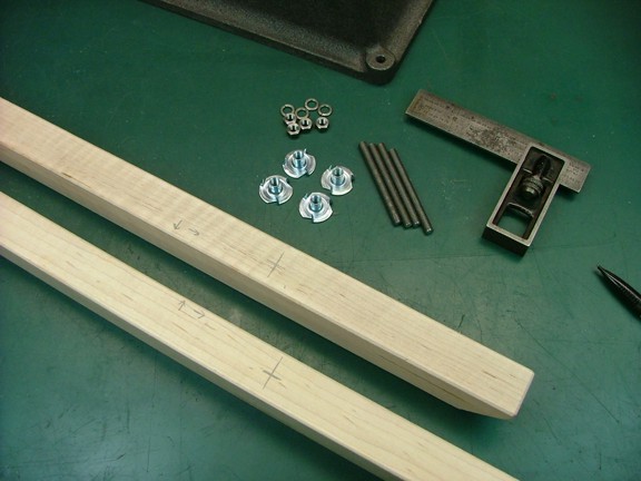
I now laid out the four mounting holes on the skids so that the mixer side of the engine is 4.5 back from the end of the skids (as the manual suggests). I then transferred the holes in the engine base to the skids for drilling (not shown). I will be using a set of 10-32 x 2.040 long studs to secure the engine to the skids. The bottom of the studs will use 10-32 blind nuts and the top side will use a set of 10-32 nuts that I machined out of the left over 9/32 steel hex stock that was included in the materials kit.
|
|
|
 |
|
|
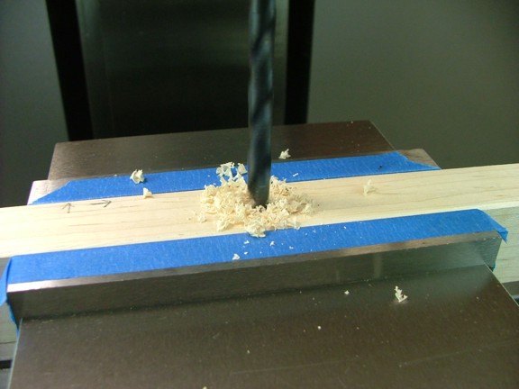
I moved the skids over to the mill so that I could drill out the 1/4 holes for the blind nuts...
|
|
|
 |
|
|
 |
|
|
I now installed the blind nuts using the milling vise as a press...
|
|
|
 |
|
|
 |
|
|
Lastly I installed a set of rubber feet that will help absorb the vibration of the engine as it runs. This is an important feature as your expensive engine could walk right off a table while running without good rubber feet. Note: The rubber feet used here are made by Shepherd Hardware Products (Cat# 9644) and were mounted at a 1 offset outside of the 10-32 studs as seen below.
|
|
|
 |
|
|
At this point I removed the rubber feet and applied three solid coats of Minwax clear satin polyurethane to seal the skids (not shown). This will keep the skids looking good even when they are covered in motor oil ;0)
|
|
|
 |
|
|
I am now very close to assembling the engine. I just have to paint the parts and then put the engine together. It wont be long now!!!
Please join me again when I put this beauty together for the last time ;0)
Till then be well my friends!!!
Don R. Giandomenico
|
|
|
|
|
|
|
|
|