 |
|
|
|
|
|
|
|
|
 |
|
|
 |
|
 |
|
 |
|
|
|
Posted on October 15, 2012:
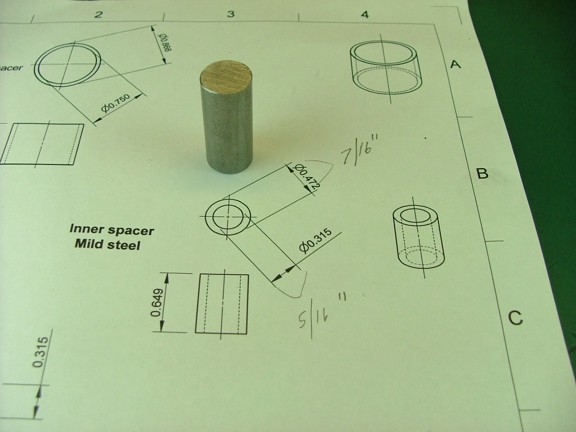
Hello again folks! I only have a few parts left to build for the magneto assembly so I wont waste any time. The next part to build is the inner spacer for the points cam. This part is made from a piece of 1/2 mild steel rod that is included in the magneto kit (seen below).
|
|
|
 |
|
|
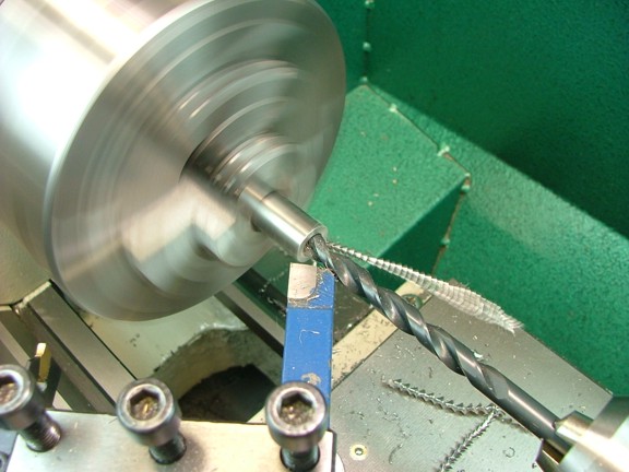
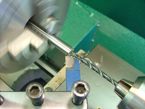
The first step is to drill a 19/64 hole straight through the rod.
|
|
|
 |
|
|
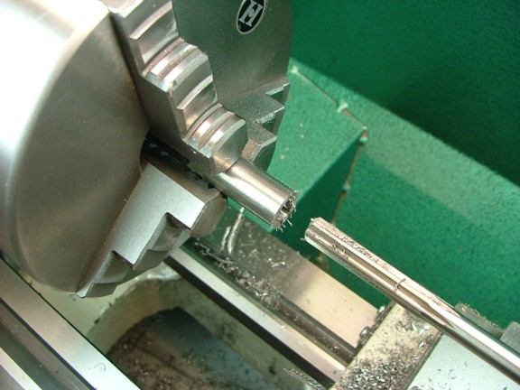
The next step is to ream an 8 mm hole for the metric rotor shaft. I do not have a metric chucking reamer so I opted to use a +.001 oversized 5/16 chucking reamer (7.96 mm) to get me close to 8 mm as possible.
|
|
|
 |
|
|
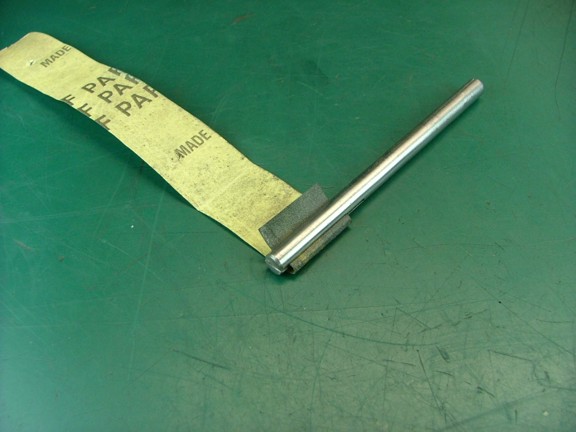
To fine tune the bore of the spacer I decided to use some sandpaper on a 1/4 slotted honing arbor. Its not a high tech solution but it works ;0)
|
|
|
 |
|
|
 |
|
|
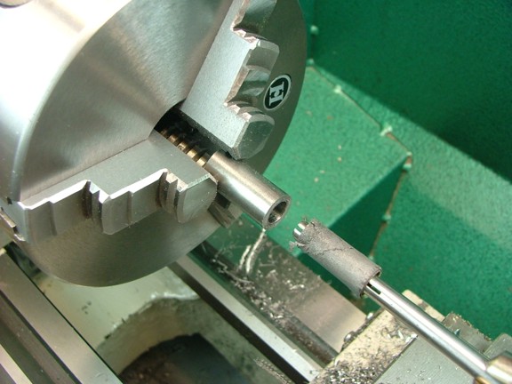
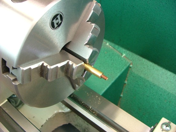
I tested the bore of the spacer with the kit supplied 8 mm shaft to ensure the hole was large enough...
|
|
|
 |
|
|
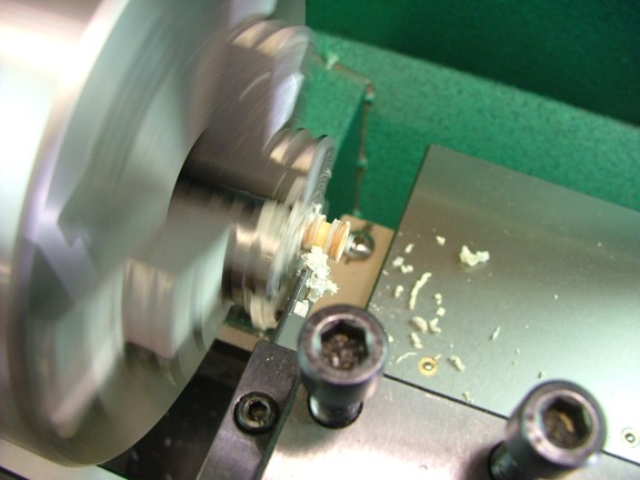
The next step is to turn the OD of the spacer down to .436 so it will fit into the cam I made earlier. After cutting the OD I fine tuned the diameter with some 320 grit sandpaper to allow a smooth fit of the cam. Note: This spacer was originally designed to have an OD of .472 but I changed that a little by making the ID of the cam smaller.
|
|
|
 |
|
|
The spacer now needs to be parted off at a length of .660...
|
|
|
 |
|
|
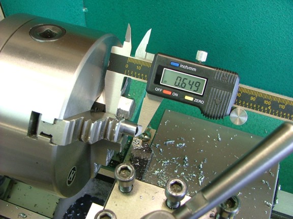
Next I fine tuned the length of the spacer to .649 which matches the outer bearing spacer perfectly.
|
|
|
 |
|
|
I tested the fit of the cam and all looks good :0)
|
|
|
 |
|
|
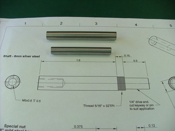
The next step is to machine the rotor shaft. The kit comes with a piece of 8 mm ground rod (below - bottom) however the original design will not work for my application. I need to fabricate a new style rotor shaft that does not need a lock nut on the outside of the magneto to secure the shaft. I have decided to make my rotor shaft out of a larger diameter rod so that I can machine a shoulder on the end for securing the bearings to the rotor.
I will be using a 3/8 x 3 piece of 303 stainless steel rod for my rotor shaft (below - top) of which I will machine to fit the 8 mm bearings as the plans require.
|
|
|
 |
|
|
The first step is to drill a #20 hole in one end of the shaft to a depth of .575. I used some cutting oil to help the process...
|
|
|
 |
|
|
Next I needed to tap the hole for the supplied rotor screw which happens to have a M5 x 0.8 thread. I tapped the hole with a two-flute M5 tap which was hand fed into the shaft by turning the chuck manually. Note: I decided to buy the correct tap for this hole as the rotor screw has been factory matched to the hub of the rotor.
|
|
|
 |
|
|
The next step is to turn down the OD of the shaft so it will fit into the 8 x 22 mm bearings supplied with the kit. I laid out a mark on the shaft at 1.600 from the end and then used a 82° countersink bit to chamfer the threaded end so it could be used on a live center (not shown).
|
|
|
 |
|
|
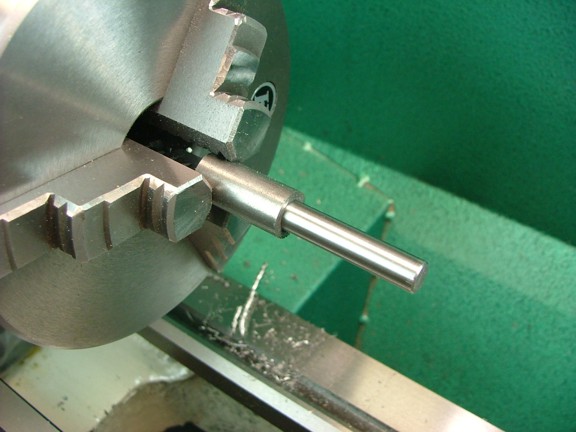
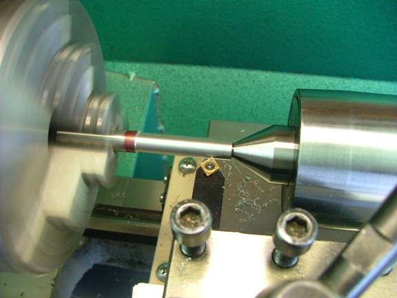
I supported the tail end of the rotor shaft and began to cut the OD down to 8 mm as seen below...
|
|
|
 |
|
|
I turned the shaft at about 480 RPM with a feed rate of .003 IPR. I made .004 deep cuts each pass which provided the best finish for the 303 stainless.
|
|
|
 |
|
|
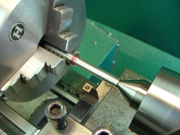
Once I got close to the 8 mm OD I used some 320 grit sandpaper to fine tune the shaft for a perfect fit of the bearings (about .313). I started on the end and worked my way inboard until the bearings fit all the way down the shaft.
|
|
|
 |
|
|
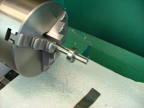
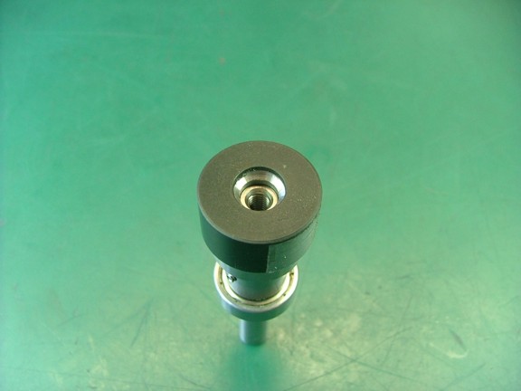
I now installed the cam, spacer, bearings and rotor on the shaft for a fit check. You will notice that the shaft does not extend all the way to the end of the rotor. This is so the rotor screw does not bottom out on the shaft and allows it to secure the whole assembly against the shoulder of the shaft.
|
|
|
 |
|
|
 |
|
|
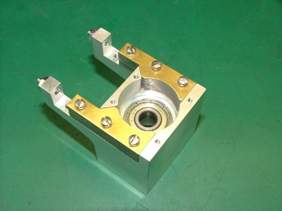
The next step is to test the assembly inside the magneto body so I installed the inner bearing by pressing it into place with a deep socket (not shown).
|
|
|
 |
|
|
Next I installed the rotor shaft, outer bearing, cam and spacer into the body...
|
|
|
 |
|
|
Lastly I installed the rotor and rotor screw. I snugged up the screw and then turned the shaft to see if the rotor was rubbing anywhere. Luckily there were no problems so I could move on to finishing the points.
|
|
|
 |
|
|
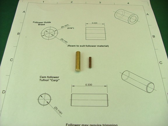
The next step is to machine the follower guide which is made from a piece of 1/4 brass rod (supplied with the kit).
|
|
|
 |
|
|
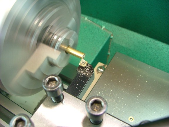
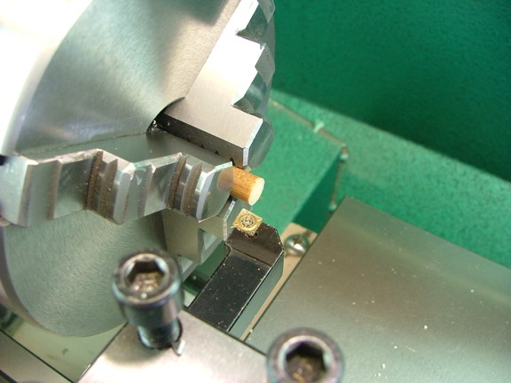
I started out by machining one end of the rod square...
|
|
|
 |
|
|
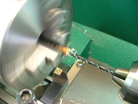
Next I needed to drill out a hole for the 3 mm Tufnol follower material (supplied with the kit) into the follower guide bushing. The actual diameter of the Tufnol material can vary so I measured the piece I had to an OD of .119. This equated to about a #31 drill bit so I drilled a .120 diameter hole to a depth of .400 in one end of the brass rod.
Note: Tufnol is a phenolic material much like Garolite. In fact you can use 1/8 G-11 Garolite as a substitute for the supplied material...
|
|
|
 |
|
|
I Now verified that the follower fit into the hole of the bushing before moving on...
|
|
|
 |
|
|
The next step is to turn down the OD of the guide to .188 so it can be pressed into the magneto body.
|
|
|
 |
|
|
The last step is to part off the follower guide at a length of .220.
|
|
|
 |
|
|
The guide is now ready to be pressed into the magneto body.
|
|
|
 |
|
|
I used my arbor press to push down the guide flush with the magneto body as seen below.
|
|
|
 |
|
|
The next part to machine is the points spacer. This part is made from a piece of 5/16 Tufnol rod which is supplied with the kit.
|
|
|
 |
|
|
I squared up one end on the lathe...
|
|
|
 |
|
|
I then drilled a #23 hole in one end to a depth of .250...
|
|
|
 |
|
|
Lastly I parted the spacer off at a length of .125.
|
|
|
 |
|
|
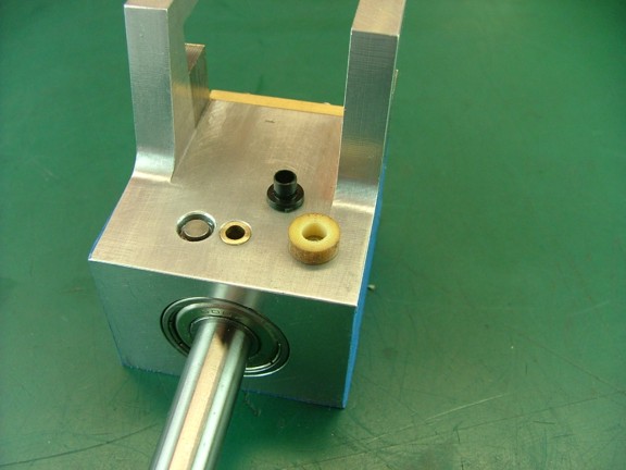
The kit is supplied with a Nylon T shaped bushing (seen below) which should fit into the Tufnol spacer. This assembly will act as a insulator for the points spring.
|
|
|
 |
|
|
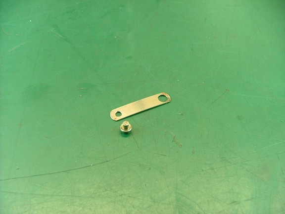
The next part to work on is the points spring. This is made from a piece of .2 x .020 stainless steel that is included in the kit.
|
|
|
 |
|
|
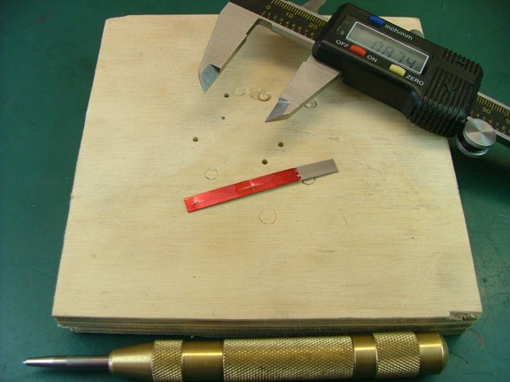
I laid out the points hole at .125 from the end (left) and then marked the insulator hole at .875 from the end as well (.750 hole to hole). I then center punched the holes for drilling.
|
|
|
 |
|
|
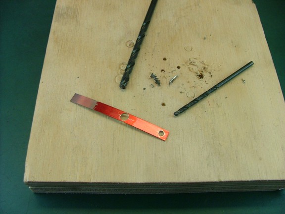
I now drilled the points hole with a #42 drill bit and the insulator hole with a #24 drill bit as seen below.
|
|
|
 |
|
|
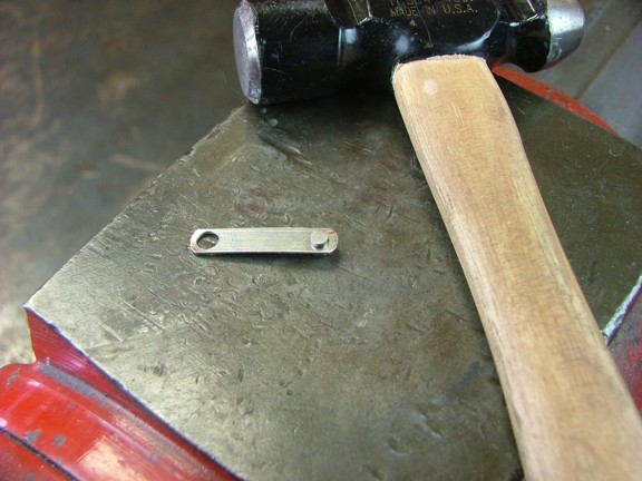
I trimmed the spring down to the proper length and then rounded off the ends on my belt sander as seen below.
|
|
|
 |
|
|
The last step is to install the points contact. I did this by installing the point into the spring and then partially flattening out the malleable steel side of the points with a hammer as seen below.
|
|
|
 |
|
|
A quick test fit of the spring revealed a nice level alignment with the magneto body.
|
|
|
 |
|
|
The next step is to cut the follower to the proper length. I started out by turning the cam until the follower was at the bottom of the cams flat. I then marked the follower at the height of the spacer and cut it to that length.
|
|
|
 |
|
|
The points gap adjustment is made by trimming the length of the follower so I set up my dial indicator to see how wide the points were spreading with the current follower length. I then trimmed down the follower until the points gap was opening to .006 as the instructions suggest.
Note: You may wish to set the gap to .008 as the follower will wear a bit during break in. If the follower becomes too short after break in you can make minor adjustments in the gap by bending the end of the points spring. If the gap becomes too narrow I would suggest making a new follower so the points contacts are kept parallel to each other...
|
|
|
 |
|
|
The next step is to solder the black coil lead to the supplied soldering tag and then mount it under the points insulator (next to the points spring). Note: I added a #4 washer under the head of the 4-40 screw as seen below.
|
|
|
 |
|
|
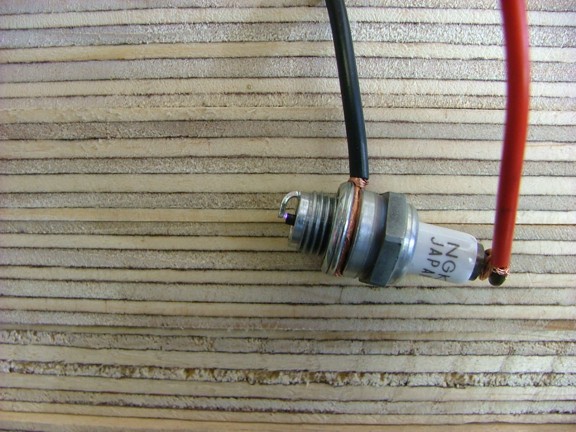
The last step in the magneto build is to set the magnetic timing of the rotor. To do this I will need to set up a spark plug on the HT lead of the magneto. I took my CM-6 plug from my engine and set the points gap to .015 which is the recommended gap for the CM-6 plug (according to the instruction manual).
|
|
|
 |
|
|
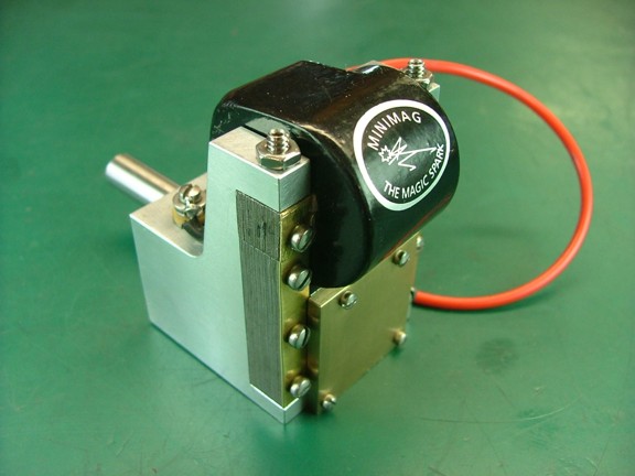
I set up the magneto in my lathe and supported the body with a stack of plywood pieces as seen below. The plywood will keep the magneto body from spinning when I set the timing. I also attached the spark plug to the HT lead as well as a ground wire that was attached under one of the coil ear locknuts. I am now ready to set the magnetic timing.
|
|
|
 |
|
|
The first thing to determine is what direction the magneto will be driven. I will be driving my magneto counterclockwise (as seen from the front of the shaft) so that is the direction I will be turning the spindle of the lathe for testing. I spun up the lathe to 350 RPM and inspected the points gap to make sure they were opening and closing correctly. I then stopped the lathe to loosen the cam adjusting screw through the adjustment hole and then moved the cam in 15° increments to see when I was starting to get a spark.
The magneto was beginning to come to life as I progressed in advancing the cams position on the inner spacer. I continued to adjust the cam until I found a sweet spot where the magneto would make a nice hot spark at the lowest possible RPM. When I was finished I was able to get a spark every rotation at 240 RPM which is pretty darn slow!!!
|
|
|
 |
|
|
I now have a working magneto to drive the spark plug. Now I am challenged with the task of mounting it to the engine which wont be easy.
|
|
|
 |
|
|
Please join me again for the next episode of the Red Wing project. Until then take care my friends!!!
Don R. Giandomenico
|
|
|
|
|
|
|
|
|