|
|
|
|
|
 |
 |
|
Page 3
|
|
 |
 |
|
The Y axis stepper motor was the next item to work on. The assembly instructions suggest that the drive pulley be installed on the shaft before installation of the motor. I found it easier to install the motor first and position the pulley in relation to top of the Y axis frame.
|
 |
 |
|
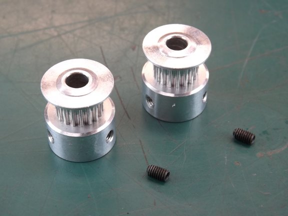
I gathered up four M3 x 14mm cap screws and washers and attached the motor to the frame. I then gathered the two 18 tooth GT2 timing belt pulleys (seen below) and set screws for installation. You will notice that the pulleys provided have two holes each for set screws but only one set screw is used per pulley. This is probably OK however I opted to add the second M3 set screw (not shown) to help secure the pulley. Once again there is a lot of force that the stepper motors transmit through these pulleys with hundreds of thousands of direction changes each print that can loosen hardware over time. Better safe than sorry...
|
 |
|
|
 |
 |
 |
|
Next I installed one of the pulleys so that the top edge of the pulley was 14.8mm from the top of the frame as seen below. This will align the timing belt to track in the center of the pulley. I applied some blue threadlocker to the set screws and secured the pulley to the shaft. The cap screws securing the motor will be tightened later after the belt has been installed.
|
 |
 |
|
The next step was to install the X axis stepper motor. This installation requires three M3 x 12mm screws, one M3 x 8mm screw and four M3 washers.
|
 |
 |
|
The short cap screw ends up going into the milled pocket nearest the linear rail as seen below. This is done for linear carriage clearance.
|
 |
 |
|
Once again I used my digital calipers to measure 14.8mm up from the tooling plate to set the height of the timing pulley.
|
 |
 |
|
I applied blue threadlocker to both set screws before tightening them.
|
 |
 |
|
Next I installed the X axis idler bearing assembly making sure to not scratch the anodized surface of the machine.
|
 |
 |
|
I now installed a M6 Nylock nut and washer to hold the idler stud in place.
|
 |
 |
|
No threadlocker was needed here as the Nylock nut has a good grip on the threads of the stud.
|
 |
 |
|
The next step was to tackle is the extruder mounting plate assembly. I gathered up the 630mm belt and the X axis end stop as seen below.
|
 |
 |
|
The X axis end stop was prepared by installing two M3 Nylock nuts into the stop as seen below.
|
 |
 |
|
The end stop was then attached to the mounting plate with two M3 x 16mm cap screws.
|
 |
 |
|
Next the timing belt clamp was then attached to the plate with four M2 x 16mm cap screws. No washers were used as the screws used here were a little too short to accommodate them. I see no issue with that however I normally like to see washers on plastic parts as a general rule.
|
 |
 |
|
The extruder motor clamp was next to install. This part is also a PLA printed part supplied by MakerGear. I secured the clamp with two M3 x 12mm screws, two M3 x 14mm screws a two M3 washers.
|
 |
 |
|
The washers and longer screws go to the exposed back side of the clamp (seen below). The other 12mm screws do not have washers as their is no room for them inside the clamp.
|
 |
 |
|
The mounting plate and clamp were now attached to the carriage. A very small amount of blue threadlocker was used on the screws (not shown). I was careful not to get any on the plastic parts which might cause deterioration of the plastic over time.
|
 |
 |
|
The timing belt was now installed over the pulleys.
|
 |
 |
|
I moved the carriage to both ends of the rail to observe the tracking of the belt in the motor pulley. Luckily the belt stayed right in the middle of the pulley as seen below.
|
 |
 |
|
I checked the idler pulley as well and found that the belt tracked perfectly in the middle of the bearings.
|
 |
 |
|
The last thing I checked was the tightness of the belt. I found that if you gently push on the belt with your finger you should be able to touch the other belt as seen below. If not, the belt is too tight and will cause premature wear on the bearings and such. Once I was happy with the belt tension I applied some blue threadlocker to the stepper motor screws one at a time and tightened them in place (not shown).
|
 |
 |
|
The next step was to install the extruder motor clamp screws. I gathered up two M4 x 35mm cap screws, two M4 Nylock nuts and Two M4 washers. The kit suggests using regular nuts for this application however I found that hardware that is tightened into plastic parts become loose much easier due to thermal expansion as well as plasticity issues.
|
 |
 |
|
I used a pair of needle nose pliers to help seat the Nylock nuts before attempting to screw in the cap screws...
|
 |
 |
|
And now for the extruder motor. The motor was positioned with the gearbox flange against the motor clamp as to keep the extruder head from being too close to the clamp. I tightened the clamp screws lightly as to not stress the motor clamp which could cause it to fail later on.
|
 |
 |
|
At this point I chose not to install the extruder assembly or the Y axis spider assembly as they could easily be damaged by accident. I will wait until more of the machine is complete before adding those assemblies.
|
 |
 |
|
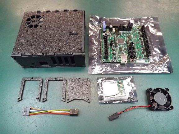
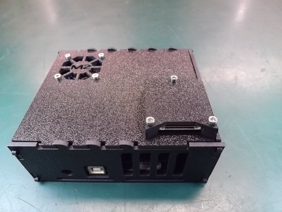
The next task to handle was to install the RAMBo motherboard controller into it’s enclosure as seen below. The kit provides a laser cut plastic box that fits nicely into the frame when assembled. Unfortunately the box is somewhat flimsy and requires a little help to make it serviceable (more on that later).
|
 |
|
|
 |
 |
 |
|
The RepRap Arduino-compatable Mother Board (RAMBo) is a very well made controller built around an Amtel ATmega2560 processor. This Arduino compatible processor is responsible for executing the G-code commands used in 3D printing. The firmware that is pre-loaded on the RAMBo board is designed to work with the MakerGear M2’s hardware configuration and is ready to work right out of the box.
The RAMBo board has many protection features including three on-board fuses, USB ground loop isolation and over voltage protection for the thermistor sensors. The RAMBo board also has five A4982 1/16th microstepping motor drivers soldered directly to the controllers four-layer printed circuit board. This will keep the drivers cooler than if they were on separate satellite boards. Cool running low-resistance MOSFET transistors control the heated build plate and extruder voltages which help keep the overall board temperatures down.
|
 |
|
|
 |
 |
 |
|
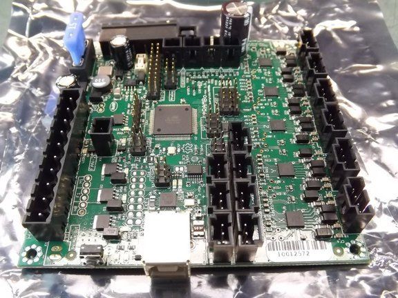
As with all electronics projects I make sure to inspect the components for issues before applying power to the circuit. I looked over the board top and bottom to make sure there were no loose pieces of solder that could ruin my expensive investment. Sure enough I found a few pieces of loose solder from the manufacturing process as seen below. They were not in a critical place although I removed them just the same.
|
 |
 |
|
The controller board is held in place with four Nylon 4-40 screws and eight nuts as seen below.
|
 |
 |
|
I installed the screws into the board and fastened a set of nuts on the bottom side of the board as seen below.
|
 |
 |
|
Next I assembled three sides of the enclosure to the bottom of the box and placed the motherboard in place.
|
 |
 |
|
I now attached the board to the enclosure with the last four 4-40 Nylon nuts...
|
 |
 |
|
The laser cut enclosure provided is designed to snap together and it does for the most part. Unfortunately the pieces are not held together very well in it’s current configuration making it flimsy. I don’t think it will be a problem in the long run although I plan to add a few screws to help secure the lid later on.
|
 |
 |
|
The next step was to add the cooling fan to the enclosure lid. Four M3 x 18mm screws, four M3 Nylock nuts and washers are used for this task.
|
 |
 |
|
The assembly instructions ask you to place the washers between the enclosure top and the fan, probably for blade clearance. The fans provided in my kit had no clearance issues so I just put the washers on the back of the fan as seen below.
|
 |
 |
|
The next project was to install the memory card reader.
|
 |
 |
|
I used a couple of pieces of “servo tape” (double sided tape) stacked on top of each other (for added thickness) to hold the reader to the top of the enclosure. This will keep the reader from moving around inside the laser cut housing provided.
|
 |
 |
|
I placed the housing in place (with the screws) before sticking the board to the top as seen below...
|
 |
 |
|
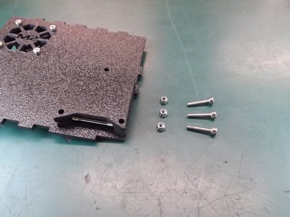
And now to finish off the reader with three M3 x 16mm screws and nuts.
|
 |
|
|
 |
 |
 |
|
Note: The main purpose of the card reader on a 3D printer is to load the G-code files (printing instructions) into the machine. If one were to want to print directly from their printer without the aid of a computer you would need a RepRap compatible LCD display unit of which MakerGear sells (Ultimachine.com also sells a RAMBo compatible LCD display as well). Then you could load your G-code from this card reader and operate the machine from the LCD display unit without the aid of a computer.
The card reader can also be accessed from your connected PC via the “host” (user interface) software. Your G-code files can then be “linked” from the card reader to the RAMBo board directly without “streaming” the G-code from your computer during a print. This is especially useful if you have large G-code files that could be effected by your PC’s performance. If your computer crashes during a large print you could loose the job and have to start all over again.
By loading G-code from the M2’s card reader and starting a print with your PC the machine can complete the print without the aid of the PC from there on. I personally plan to stream my G-code files directly from my laptop without the aid of the card reader. I don’t anticipate any issues caused by computer stability or communication latency so unless it’s a large print I will forgo the card reader option for now.
|
 |
|
|
 |
 |
 |
|
The next step was to attach the enclosure to the M2’s frame. This is done with three M4 x 16mm cap screws, three M4 Nylock nuts and six M4 washers.
|
 |
 |
|
When I placed my enclosure into the frame I noticed that the holes were misaligned slightly and an adjustment will have to be made.
|
 |
 |
|
To fix the alignment issue I used a X-Acto knife to elongate the three mounting holes as seen below.
|
 |
 |
|
I now placed the three screws in the frame with one black washer on the outside and two stainless ones per screw on the inside as seen below.
|
 |
 |
|
And now for the Nylock nuts...
|
 |
 |
|
The enclosure top is designed to be held in place by some keeper tabs that are seen in the photo below. Unfortunately there is nothing keeping the top from sliding out of its keepers which is why I will be adding some screws to keep it in place.
|
 |
 |
|
I decided to use a set of circuit board carbide drills to make a set of tiny holes in the lid for a set of miniature screws.
|
 |
 |
|
I drilled a small hole into the side of the lid and into vertical wall of the enclosure as seen below. I then widened out the hole in the lid to accommodate the screw.
|
 |
 |
|
I repeated the process for the other side of the enclosure and then installed the screws.
|
 |
 |
|
Now the enclosure feels much more solid than before.
|
|