|
|
|
|
|
 |
 |
|
Page 2
|
|
 |
 |
|
The basic reason for this article is to document my experience building the MakerGear M2 printer. As usual I will be adding my own modifications and upgrades as I progress through the build. These modifications are just ideas and methods that I personally prefer to add to my machine and are not required to assemble a working printer. The M2 by itself is a great machine and will work terrifically as-is, right out of the box.
Note: The modifications made to the MakerGear M2 in this article are not endorsed by the manufacturer and may void any warranties that cover the machine from manufacturer’s defects. It is important that you follow the manufacturer’s assembly instructions to insure that you will be covered by MakerGear’s warranty policy. If you are in doubt about what is an acceptable modification to your machine you can easily contact MakerGear for clarification on the matter.
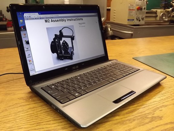
To get started on my project I wanted to look through the MakerGear M2 Assembly Instructions to see what I was in for on this build. I think it is important to review instructions in entirety before attempting to build anything as you are more likely to discover issues before you get to them. At my work (IBEW electrician) I like to review the construction drawings including other trades to help me fully understand how a building will be built. This extra knowledge is helpful when making decisions about future tasks and usually saves time in the long run.
|
 |
|
|
 |
 |
 |
|
Once I fully reviewed the instructions I was ready for the build. The workbench was cleaned and my tools were organized. I was ready to go!!!
|
 |
 |
|
To help speed up the assembly time I decided to cut the tops off of the sealed hardware bags and set them in plastic bins according to their thread size.
|
 |
 |
|
As you may already know, I am a real organizational freak as everything has it’s place. I cannot operate unless I know everything is accounted for ;0P
|
 |
 |
|
The manual suggests starting with the belt assemblies so I grabbed the two identical 3D printed GT2 timing belt clamps and hardware as suggested. I used an M2 x 16mm cap screw as a handle to push in the eight M2 nuts into the “nut holes” on the belt clamps as seen below. Using a screw threaded into the nut will help ensure the nut is aligned correctly reducing the possibility of cross threading later on.
|
 |
 |
|
The M2 uses two sizes of GT2 timing belts, a 630mm belt and a 702mm belt. These belts are slightly different in thickness and need to be fitted to the belt clamps to eliminate backlash. In my kit the 630mm belt was too thin to fit tightly into it’s belt clamp so I needed to shim it with a piece of printer paper.
|
 |
 |
|
I cut s trip of paper and placed it behind the belt (on the flat side) to take up the gap and make a tight grip on the belt.
|
 |
 |
|
The ultimate goal with any precise machine is to eliminate any play in the mechanism to improve accuracy and reduce wear. The drive belts on the M2 will be taking the brunt of the force required to drive the X and Y axis of the machine and must be set up right to offer proper service life.
|
 |
 |
|
The 702mm belt did not need any adjustment so I could move on to the next step.
|
 |
 |
|
The next step was to inspect the “spider” bracket for flatness. The spider bracket is what is used to support the build platform and must be perfectly flat to ensure the build plate does not twist or rock during printing. I placed the spider on a flat surface to see it it was straight and noticed that one of the arms was bent up a little. This probably happened during shipping.
|
 |
 |
|
This bend (seen below) will unevenly support the build plate so it must be straightened before continuing with the build.
Note: It is not likely that many kits will have this issue but it’s a good idea to check anyway. If you are unsure about straightening a bent bracket you can send it to MakerGear for a replacement part.
|
 |
 |
|
To straighten my spider bracket I put a rag in the jaws of my vise (to protect the finish of the spider) and clamped the bent arm in place. I then carefully pushed the bracket straight with progressive force (it doesn’t take very much) while checking my progress against the flat surface between adjustments.
Note: If you don’t have patience for this process you are better off asking for a replacement part. You could easily ruin the spider by rushing the process...
|
 |
 |
|
Using a straight edge I was able to confirm that the spider was flat and I could continue with the build.
|
 |
 |
|
The next step was to install the build platform mounting pads. I gathered up the eight M3 x 14mm cap screws and rubber pads as seen below.
|
 |
 |
|
I installed the fasteners into the pads with some Permatex blue threadlocker (Cat #24200). This will keep the pads from becoming loose during a print and possibly damaging the machine. I use the blue threadlocker on a lot of different parts although care must be taken when using it around plastic parts as it can damage certain kinds of plastic when in direct contact.
|
 |
 |
|
The screws were installed so that they were tightened only a 1/2 turn beyond the first contact with the rubber as to not deform the pads.
|
 |
 |
|
The next step was to work on the stainless steel spider mounting plate. I proceeded to install the Y axis end stop which includes a 3/8” nylon spacer, M3 x 16mm cap screw, M3 Nylock nut (washer optional).
|
 |
 |
|
The end stop was placed in the slot seen below with the screw favoring the square side of the plate. This will assure the end stop will correctly contact the limit switch later on...
|
 |
 |
|
The use of the washer on the spacer is optional although I prefer using washers to spread out the force of a fastener on plastic parts.
|
 |
 |
|
The next step was to attach the 702mm belt assembly to the mounting plate with four M2 x 16mm cap screws and washers.
|
 |
 |
|
In this case the M2 washers are necessary to keep the screws from protruding too far past the belt clamp and scraping the Y axis tool plate.
|
 |
 |
|
The next thing to do was attach the spider to the mounting plate. This is done with three wave springs, 1/8” Nylon spacers and M3 x 12mm screws (M3 washers optional).
|
 |
 |
|
The 1/8” Nylon spacers are used to center the wave springs as seen below.
|
 |
 |
|
I installed the three M3 cap screws and ran them in them until they just contacted the Nylon spacers. These screws will be adjusted later to level the build platform so no need to “tighten” them now...
|
 |
 |
|
I applied blue threadlocker to these screws (not shown) so they do not have the tendency to move during printing later on. Note: The blue Permatex threadlocker compound is soft enough to allow easy adjustment later on...
|
 |
 |
|
The spider assembly was now put aside while I looked over the machine for possible improvements. I decided to install washers on all of the end stops while making sure the rail carriages did not slide off of the rails. This is not necessary just a pet peeve of mine...
|
 |
 |
|
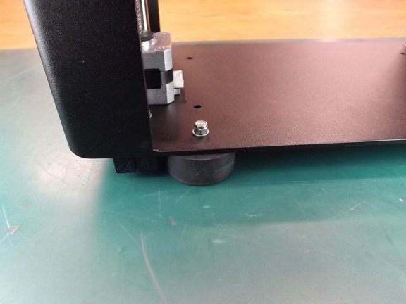
The next item that sort of bothered me was the offset rubber foot that was obviously displaced by the Z-axis linear rod mounting bracket seen below. All of the other feet are towards to outer perimeter of the machine except this one. It seems that this could cause an unstable footing for the printer which explains the stick-on rubber feet they added to the bracket in the upper left of the photo below.
|
 |
 |
|
I decided to relocate the rubber foot closer to the front of the machine so I removed the foot and the stick-on feet from the machine as seen below...
|
 |
 |
|
I removed the linear rod clamp screw (not shown) and reinstalled it so it was not interfering with the new location of the rubber foot. I then marked the new location of the foot at 65mm x 15mm off of the corner of the machine.
|
 |
 |
|
I used a 7/64” drill bit to make a pilot hole and then used a 5/32” to widen the hole. I used a bit of Rapid Tap cutting oil (not shown) to make the hole as stainless can work-harden and ruin your drill bits unexpectedly.
|
 |
 |
|
The rubber foot was now reinstalled with the original hardware...
|
 |
 |
|
The machine is now much more stable which will help keep it from rocking during rapid movement of the axis during printing.
|
 |
|
|
 |
 |
 |
|
The next project to tackle was the idler pulley bearings. These bearings along with the X and Y motors will handle all of the force applied to the carriages. If you’ve ever seen rapid 3D printing you would know that there can be quite a lot of force required to make very sharp and abrupt direction changes at high acceleration. Because of these forces the drivetrain for these axis must be solid and reliable for daily printing use.
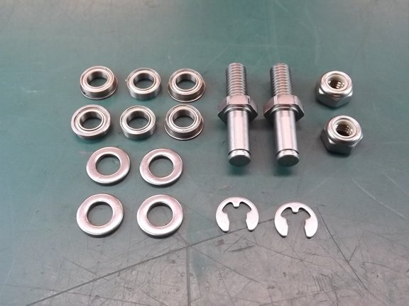
The MakerGear M2 has a very solid system for keeping the timing belts tight and in place however the idler bearing assembly could use a little help (IMHO). The assembly consists of three bearings, two of which have flanges as to keep the belt from coming off the pulley. All three bearings are stacked atop one another to create the idler pulley however the washers provided to be used as shaft spacers can rub on the outer bearings races and create unnecessary friction.
|
 |
|
|
 |
 |
 |
|
To fix this friction problem I decided to create a bevel on one side of each of the four washers so that they only contact the bearing’s inner race. This will eliminate the metal to metal friction I wish to avoid. To do this I needed a grinding arbor to hold the washer for the grinding process. For this I used a 6-32 flat head screw, 6-32 nut and a 1/4-20 nut as seen below.
|
 |
 |
|
I installed the idler pulley spacer washers (one at a time) so that the 6-32 screw head was flush with the “flat” or cut side of the washer and the 1/4-20 nut under the washer to act as a spacer for the tapered bottom of the 6-32 screw head. It doesn’t look like it but there is a lip on the inside of the washer that holds the 6-32 screw from pulling through the washer. A larger flat head screw could be used although you may have to grind a bit if it away to expose the face of the washer below it...
|
 |
 |
|
Using my cordless drill I spun the arbor with the washer against my disk sander which was running at a 5° angle or so. This dual action caused the washer to be ground with a bevel into the face.
|
 |
 |
|
I ground all four washers the same way, one at a time as seen below...
|
 |
 |
|
Now the washers cannot contact the outer race of the bearings as before eliminating any grinding friction.
|
 |
 |
|
To help improve the idler bearings performance I decided to add an O-ring to create pressure on the inner races and keep them secured when assembled. I selected two 5/16” ID x 1/16” thick O-rings to be placed into the bearing assembly.
|
 |
 |
|
I installed the O-rings into the bearing assembly (seen below) which took out all of the play between the bearings making a really solid assembly. If installed correctly the bearings should move freely without any play or metal to metal grinding whatsoever.
|
 |
 |
|
The first idler pulley assembly bolted in nicely (be careful not to scratch up the tooling plate when installing this bolt). If you do a black permanent marker will fix small scratches.
|
 |
 |
|
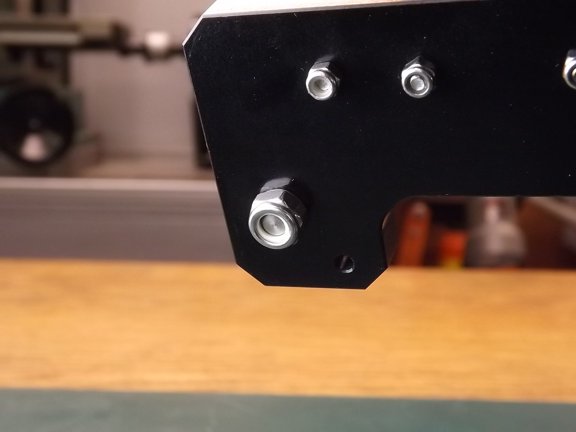
To keep the idler stud bolt in place a M6 Nylock nut is used on the bottom. I used blue threadlocker (not shown) for this nut as the Nylon locker ring does not contact the threads in this case...
|
 |
|
|
 |
 |
 |
|
Note: It is very important to make sure that there is no loose hardware on a 3D printer or else you risk the machine being damaged during a print. Parts can become loosened and start to drag on moving surfaces causing repetitive damage to important surfaces. Because the machine doesn’t know when it’s broken it can continue to grind itself apart unless you notice the malfunction and stop it yourself.
Since most of us will not want to watch a ten hour print it is safe to say most of the printing you will do will be done unattended. Because of this it is a good idea to watch the machine run for the first few layers each print to inspect for any loose or worn parts that may fail during a long print. Of course, buying a solid machine like the MakerGear M2 is added insurance against a malfunction and one of the main reasons I chose the M2 over a less sturdy design.
|
|