GR-7 Turbojet Engine Project  11/10/05

Posted on November 10, 2005

       OK, where did we leave off? Oh yes, I had just finished the oil pump assembly and was preparing to install some of the engine’s subsystems. The oil pressure switch, combustor pressure switch, fuel pump, ignition coil, and fuel control solenoids could now be mounted to the engine frame. By carefully planning their locations I just may get them all in the engine frame. This is the part that most resembles a jig saw puzzle.

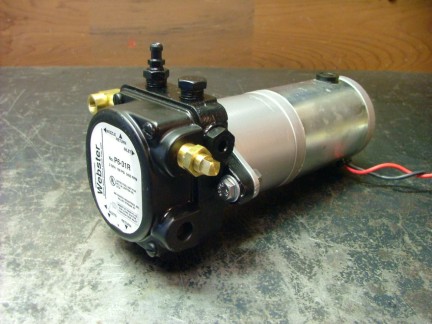
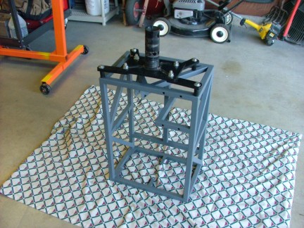
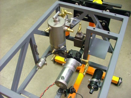
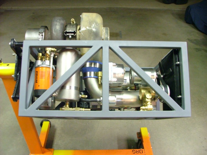
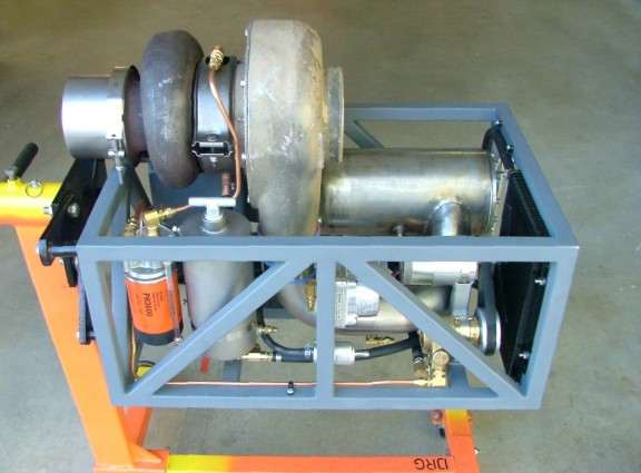
       The fuel pump was the largest component to fit into the engine frame so I decided to install it first. Before I did anything, I prepared the fuel pump by disassembling it and painting the pump drive adaptor bracket. I also installed the newer rebuilt Webster eccentric gear pump to the assembly in leu of the older pump. With the ready to run assembly complete, I planned out it’s location in the engine frame. After weighing my options I settled on installing the pump just under the combustor and inlet duct.   

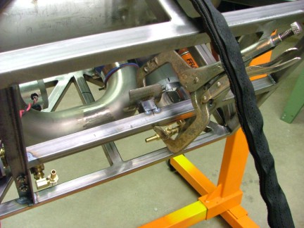
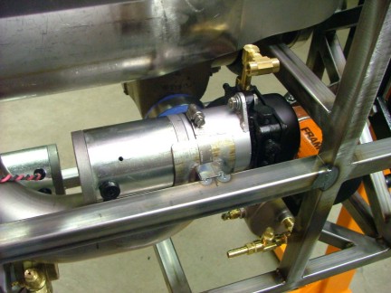
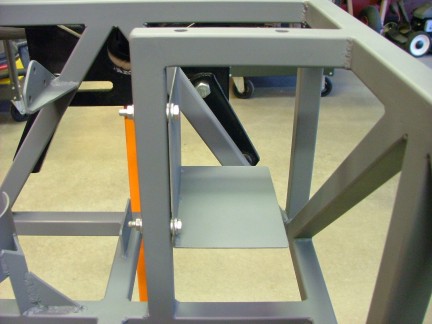
       I welded a cradle bracket to the bottom of the engine frame and test fit the pump assembly into it’s new home.

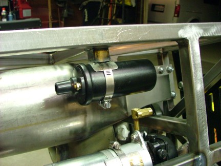
       The ignition coil was next to be fitted so I fabbed up another cradle bracket and burned it on as well. I situated the coil near where I proposed my spark plug location would be on the combustor.

       While working on the engine I noticed that a coat of rust was forming all over the frame. I did not want to have to sand blast the frame later on so I decided to strip the frame and get a coat of primer on it. I pulled all of the parts off the engine and cleaned it for paint. Once the rust was removed, I sprayed on an automotive gray primer to stop any further rust issues

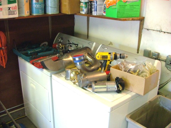
       I had set some of the engine parts on the washer/dryer while the frame was being painted. My wife Stacy was trying to get some laundry done and kindly asked me to remove the “junk” from the machines which prompted me to write my first turbine joke:
       “If your wife asks you to kindly remove the combustor from the washing machine so she can do the laundry, you might be a DIY turbine builder ;0)”

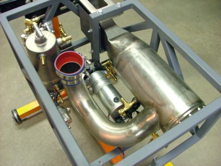
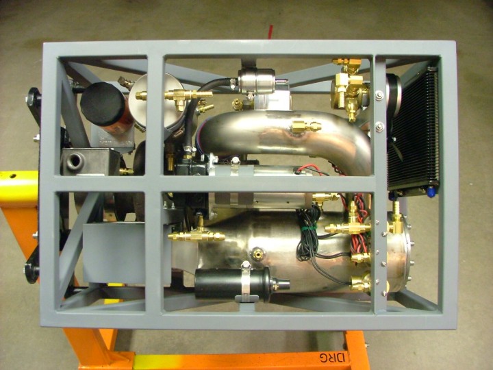
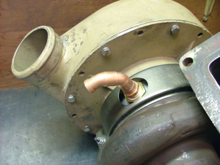
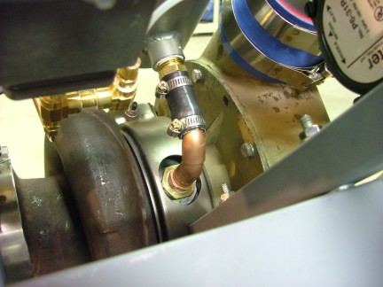
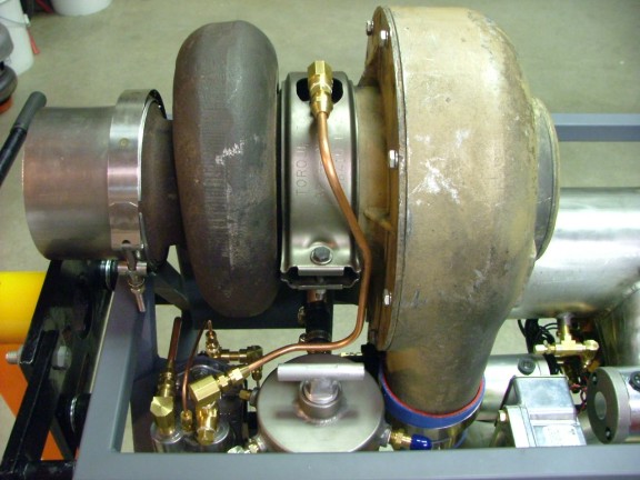
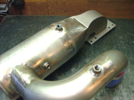
       Before I bolted the combustor back into the engine frame I needed to install the combustor drain fittings. The combustor drains will insure that there is no standing fuel in the bottom of the combustor during startup. This will prevent a “hot start” in which wet fuel is blown through the hot turbine wheel causing the engine to spit fire and overheat. I needed to install two separate drains as my inlet duct would need one as well as the combustion chamber.
       The combustion chamber was built with a slight incline to facilitate proper draining of fuel.  This allowed me to install the drains at the “low” points. I welded in some 304 half couplings that will be used later to plumb the drain system.  I also added the combustor pressure tap while I was at it. I tried to install it in a location that would have the least turbulent air flow for steady pressure measurements. You can see it just above the inlet diffuser.

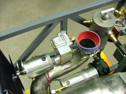
       The next step was to install a heat shield around where the combustor elbow fits into the frame. This should prevent any radiant heat from damaging any subsystems that are close to the elbow. To do this I installed a 16 gauge plate just under the elbow’s location. The heat shield  will help protect the oil pressure switch which was the next component to install.

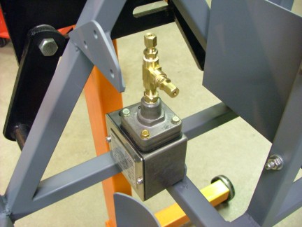
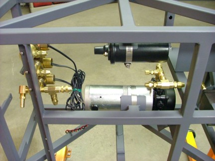
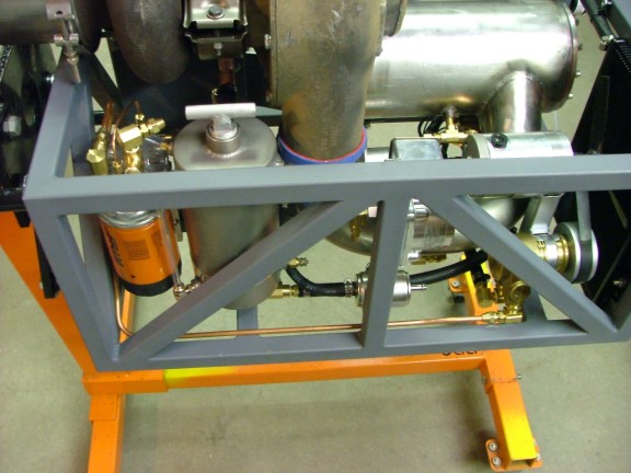
I had found a couple of nice pressure switches on eBay a while back. They are similar to the one I used on the GR-1 & GR-5A. The switches are made by Barksdale Controls (Part# E1H-H90) and feature a 3-90 PSI adjustable trip rating. You can just dial in the low oil pressure limit and go. They are a little bulky but absolutely bullet proof and reliable.

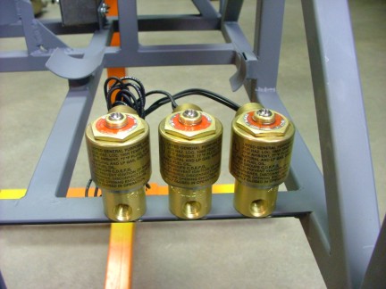
       The next components to install were the fuel control solenoids. I stumbled onto these babies in another eBay auction. They are made by the Allenair Corp. (Part# X3CBX4B) and are rated for gasoline, diesel, propane, and fuel oils. The 12V 7-Watt solenoids are rated for 150 PSI and feature 3-way valving. I am using three solenoids for the basic operation of the turbine: two for fuel control and one for a combustor auto drain. I positioned the solenoids close to where the fuel will enter the combustor end plate.

The fuel pump and the ignition coil were the next items to install.

Next followed the oil tank, oil filter and fuel filter.

Next followed the combustor assembly.

       There is a great advantage to designing your parts as modular assemblies as they can be removed and replaced much easier than an integrated system. The oil pump would be a good example as it can be unbolted in one piece and removed as a complete unit. I try to use this strategy in most of my designs.

       Last but not least, the combustor pressure switch was ready for installation. For this switch I used a Barksdale Controls (Part# D1T-A80SS) pressure/vacuum switch. The switch trip is adjustable from 0.5-80 PSI positive or negative and features stainless steel switch bellows. Once again a little bulky but absolutely bullet proof. This is the same unit used on the GR-5A engine.

       The last thing to do was install the turbo. This would complete the basic engine configuration and allow me to start plumbing the hydraulic system. Now that I know where everything goes, there should be no problem avoiding positioning conflicts.

       By now, the GR-7 was really taking shape. I decided to get the hydraulic system plumbed so I could test out the hydrostatic bearings in the VT-50 Turbo. I started out by building a drain pipe for the turbo drain. I used common copper plumbing fittings to make an elbow fitting that will connect the turbo to the oil tank. I then used a petroleum rated rubber hose to couple the elbow to the tank hose barb. Notice the use of two 45 deg. fittings instead of one 90 deg. fitting. This should help reduce flow restriction and in turn reduce the chance of leaks.

       The next step was to run the copper lines on the high pressure side of the system. I used 1/4” copper tubing in conjunction with brass flare fittings. An automotive tubing bender and a flare tool were used to create the custom lines. I used a double flare die to create the flare ends on the copper lines. The double flare helps to seal better than a single flare.

       I installed the copper lines on the engine and held them in place with tie wraps. For the low pressure side I used 3/8” transmission oil cooler hose that is rated for petroleum products. Luckily the oil cooler kit included all of the hose I needed.

       I was not sure if my proposed pump system would supply enough oil flow/pressure  to the big VT-50. The bearings in the VT-50 are almost three times the size of the T3/T4 turbo in the GR-5A engine. I would have to make sure that the pump system would be able to maintain a minimum of 40 PSI at full operating temperature. Since oil viscosity usually gets thinner at higher temperature, the turbo may need more oil flow to maintain proper pressure.
       I a am using a multi-weight oil (5W-30 fully synthetic) which should help the oil from getting thinner at operating temperature. Multi-weight oils have polymers added which “thicken” up the oil as it approaches operating temperature. I could choose to use a thicker multi-weight oil later (like 20-50) if the VT-50 has a large appetite for oil, but that is down the road.
       It was now time to fill up the oil tank and pressurize the system. I added about 3.5 quarts of 5W-30 synthetic motor oil to the system while running the oil pump. Once the air bubbles were worked out of the system I was able to set the oil pressure regulator on the oil pump. I set the pressure at 90 PSI initially to see if the pump would keep up. It seemed to do just fine so I reduced the pressure to 50 PSI (
See addendum).                                                                              

       I used my leaf blower to spool up the turbo to see if there were any visible leaks. The turbine was a little sluggish (probably from the cold oil) but spun without any play. I could not see any visible leaks from either side so that was a big plus. This was a major step for me as I can now continue forward knowing I have a good chance of making this turbo work.

       I can now get into the most involved portion of the project, the evaporator system. The evap system will probably require some trial and error to develop but I am confident that it will work in one form or another. Hopefully my combustor design will accommodate the evap system without any trouble. There is only one way to find out if it will work and that is to build it!!! Check back soon as I dive into the evaporator system and the mysterious world of thermodynamics :0)

Take care,

Don Giandomenico

[Home] [What's New At RCDON] [Articles] [Aircraft Projects] [Aircraft Videos] [Aircraft Videos II] [Experimental Projects] [GR-1 Turbojet Engine Project] [GR-5 Turboshaft Engine Project] [GR-5A Turboshaft Engine] [GRV-1 Turbotug Project] [GR-7 Turbojet Engine Project] [GRV-2 Jet Bike Project] [GR-6 Turboshaft Engine Project] [GR Engine Series Q&A] [Readers Projects] [Experimental Projects II] [My Collection] [RC Links] [About Myself] [Contact RCDON]