My original goal with this engine was to create a combustor that would be able to burn diesel fuel, kerosene or Jet-A. Unlike the propane gas I am using in the GR-5A, diesel/kero fuel requires some kind of atomization or vaporization before it can be effectively burned in a combustor. My plan is to develop an evaporation system to process the liquid fuel for combustion. I had researched a couple of evaporation systems from commercial engines to get a basic idea of how they worked.
From what I understand, an evap system uses combustor heat to vaporize a spray or stream of liquid fuel thus making it ready for the combustion cycle. The evaporation process is done mainly with the use of an evaporator tube assembly. In essence, fuel is sprayed into a heated tube and while it travels along its length is boiled into an vaporized state. The evaporator tube or tubes are placed in a location where the flame of the combustor is in contact with them. Suspended in each tube is a fuel injector which can deliver a coarse fuel spray into the evap tube. Combustion air is routed around the injector and mixes with the fuel vapor, propelling it into the combustor. The fuel injector is placed on the cool side of the evap tube, most likely at the base or end of the burner can, outside of the combustion liner. The hot end of the evaporator tube is routed so that it will supply the vaporized fuel needed to burn in the combustor and also supply enough heat to warm the evaporator tubes themselves. Evap tubes are typically designed to be cooled by the combustion air/fuel mixture flowing through them. This is what ultimately keeps the tubes from burning up in the combustor. The alternative to an evaporator system would be an atomization system in where liquid fuel is directly sprayed into the combustor. This is done with a high pressure fuel pump and spray nozzle. Fuel droplets are created by the nozzle or nozzles and are burned in the combustor. This system is utilized by most commercial jet engines as it is simple and reliable. However, the evaporation process has a couple of key advantages over the atomization system.
One advantage is that the fuel pressure required to feed the evaporator system is much lower than that of an atomization system. The pressure required to inject fuel into the evap tubes need not be much higher than the combustors normal operating pressure. This pressure could be as low as 25 PSI in a small gas turbine which in turn reduces on-board power requirements for the fuel pump system. This is more important with the smaller gas turbine engines where auxiliary power is at a minimum. Another advantage to the evap system is that it allows smaller combustor designs to work with liquid fuel. Small combustors can have difficulty burning fuel delivered by an atomization system. This is because the fuel droplets created by the atomizing nozzles are too large in relation to the size of the combustor. There is simply not enough room to effectively burn the fuel droplets within the combustors burner can thus causing turbine overheating. Some turbine experimenters have dodged this problem by using super high pressure fuel pumps to deliver 500 to 800 PSI of fuel to an undersized fuel nozzle. This combination can reduce the size of the fuel droplets which also reduces the space and time it takes to burn them within the burner can. This unfortunately requires a great deal of auxiliary energy of which I wont have on my proposed jet bike. This is why I have settled on the evaporator system for my fuel delivery. Sorry for getting long-winded :0) Anyway, to get started I needed to build an injector base that will house the fuel injectors and serve as a combustion air plenum for the evap tubes. The plenum will route some of the incoming air charge to the evap tubes which in turn will propel the fuel vapor into the combustor. This injector base will house two fuel nozzles, one for the evap tube assembly and one for a pilot flame. The pilot flame nozzle will create a fine spray of fuel which will be ignited by a modified spark plug.
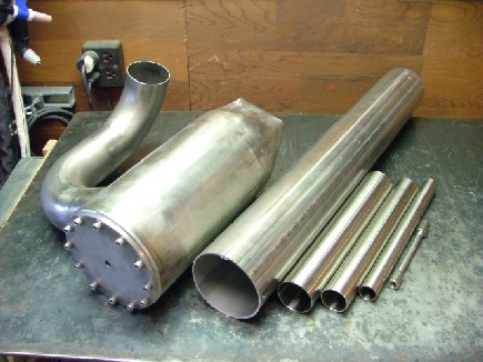
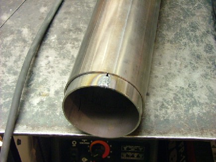
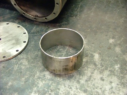
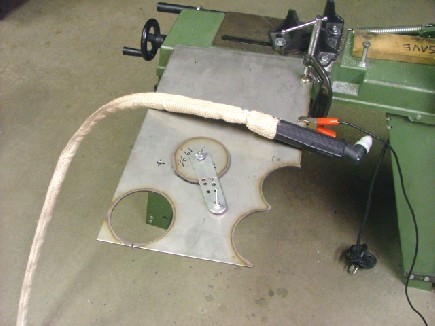
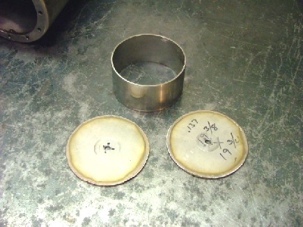
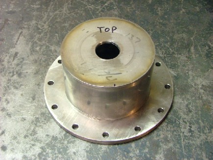
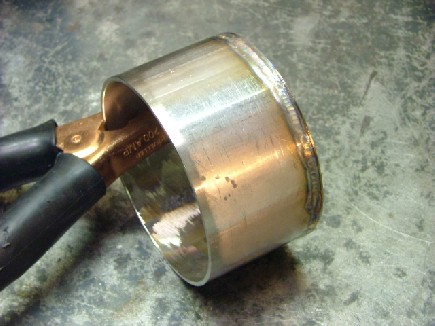
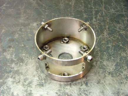
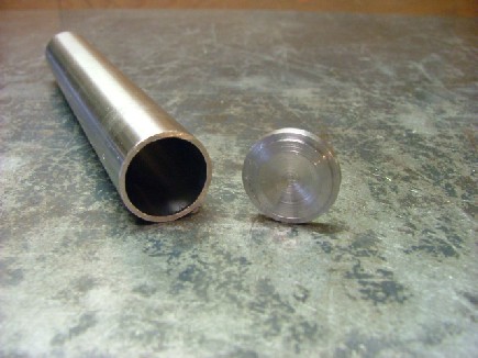
During start up, the pilot flame will heat up the evap tubes and allow them to start operating. When the engine reaches operating temperature, the pilot flame will be shut down. Sounds good on paper anyway :0) I wanted to build the injector base as a modular unit so it could be independent from the combustor end plate. This will allow me to modify or rebuild the base without affecting the combustor end plate or flame tube assembly. The injector base will also serve as a flame tube support which means that I will be able to redesign any internal component of the combustor without modifying the combustion chamber or end plate. In order to do this I needed to build a sleeve to fit into the 4 304 stainless steel flame tube. This sleeve will act as the injector base body and fit into the flame tube. I proceeded to build the sleeve by sectioning out a piece of the 4 tube and then welding it back together. The sleeve was then ground and prepared for the next step.
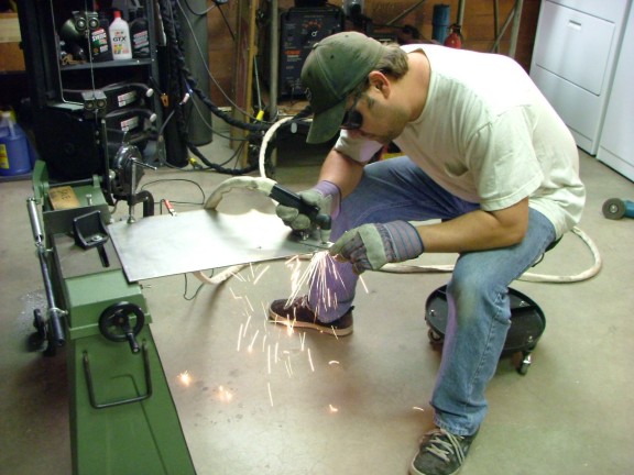
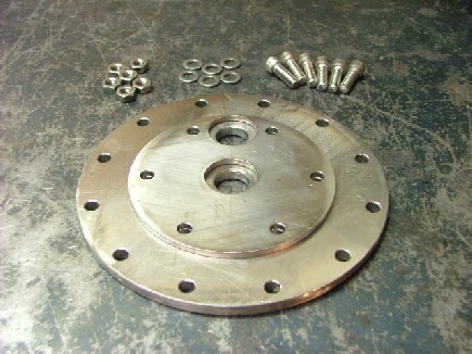
The next step was to cut out a couple of 10 gauge disks for the end plates of the base. Once again I used the plasma cutter and circle jig to zap them out.
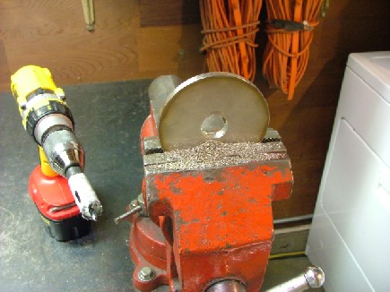
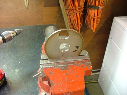
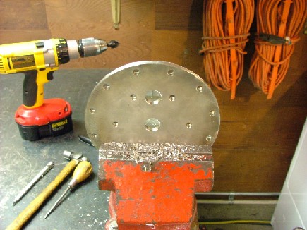
Once the disks were cut out they were cleaned up with the grinder to remove the slag. I then drilled the injector holes in the bottom and top disks.
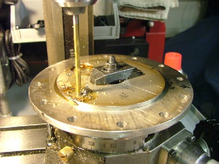
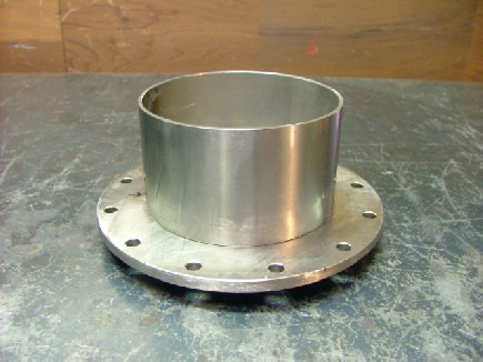
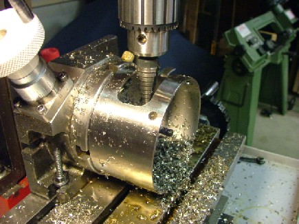
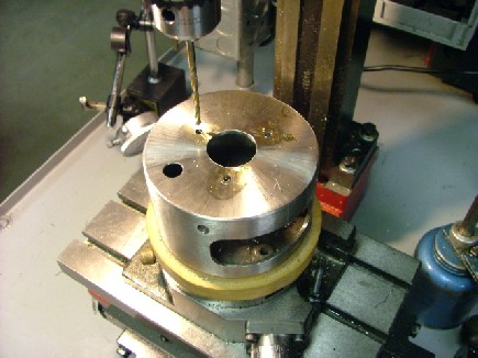
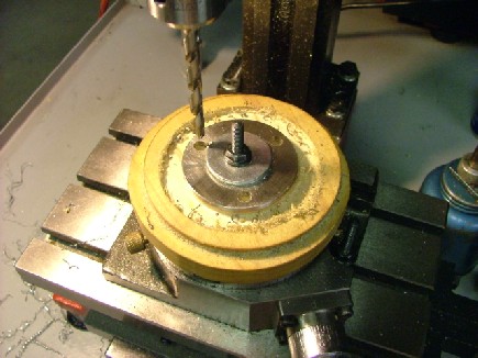
I decided to use 1/4-20 hardware to attach the injector base to the combustor end plate. I needed to index and drill the holes in the end plates for the bolts so I loaded up the rotary table. Using the table I drilled six 1/4 holes 60 degrees apart.
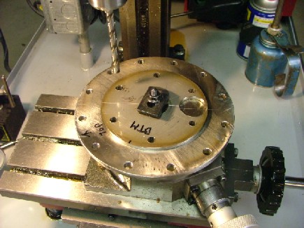
The next step was to drill the holes in the combustor end plate for the threaded couplings which will hold the injectors. I drilled the holes just slightly bigger that the 304L stainless NPT couplings I will be using.
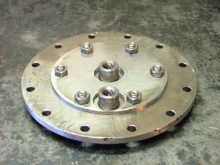
Using the TIG machine I carefully welded the hex nuts to the injector base end plate. Following that were the couplings in the combustor end plate.
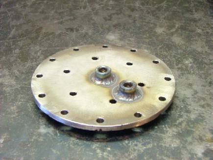
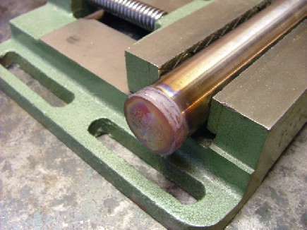
The bottom end plate was ready for welding. After cleaning the cutting oil off of the pieces I carefully welded on the plate. I was amazed at how narrow the bead can be if you carefully control the heat output.
By using my belt sander I was able to give the injector base a brushed finish. Its hard to believe how versatile the belt sander really is.
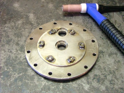
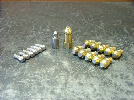
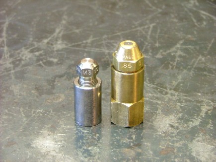
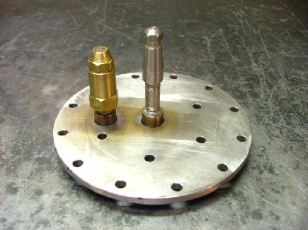
For my fuel injection I decided to use two different types of nozzles. A fuel oil furnace nozzle and an industrial misting nozzle. The furnace nozzle will be used as a pilot flame nozzle and the misting nozzle will be used for the evap tube injector. The pilot flame nozzle needs to have a very low GPH (Gallon Per Hour) rating as to not flood out the combustor ignition system during startup. For this nozzle I am going to use a Delavan furnace nozzle. I had purchased an assortment of Delavan nozzles on eBay a few moths back and now was the time to experiment with them. I picked out a nozzle with a 0.5 GPH rating (@ 100 PSI) and an 85 deg. hollow cone spray pattern (Type A). This combination will produce a very fine fuel mist which is optimum for a spark plug ignition system. An open spark should be able to ignite the fuel spray in the combustor which will eliminate the need for a propane gas starting system. For the evap tube injector I will be using a Hago industrial misting nozzle. The Hago type M nozzle was designed for general low-cost misting. I will be using the nozzle to provide a coarse spray of fuel inside of the evap tube assembly. The advantage of the Hago nozzle is that it is much smaller than the Delavan in diameter which will allow it to fit into a smaller evap tube. I needed an assortment of Hago nozzles for my experiments so I purchased seven different GPH rated nozzles from McMaster-Carr. The nozzles are made from a copper-nickel alloy which can help in high heat/high corrosive areas. They are available with 1 to 15 GPH (@ 100 PSI) ratings and 160 deg. or 80 deg. hollow cone spray angles. I chose to use the 80 deg. nozzles for my evap tube assembly (See addendum).
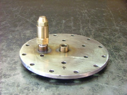
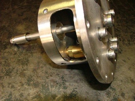
The pilot flame nozzle is mounted on the off-center threaded coupling located on the combustor end plate. This is to allow it to properly operate without being blocked by the evap tube assembly inside the combustion liner. The evap tube nozzle/injector is mounted in the center as the main evap tube assembly will be mounted over it later.
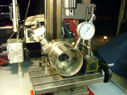
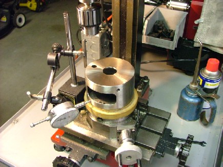
I needed to drill out my flame tube mounting holes along with the combustion air plenum port before I was able to weld on the injector base top plate. To do this I vertically mounted the injector base to my rotary table on the mill. I then drilled four 1/4 holes 90 deg. apart to accommodate the flame tube hardware.
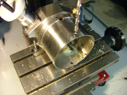
The combustion air plenum port was then milled out of the side of the injector base. I milled out a larger hole than needed as to not restrict air flow to the evap tubes. I used a Unibit step drill for an experimental mill bit which worked very well.
1/4 nuts were welded into the inside of the injector base to accommodate the 1/4-20 flame tube mounting bolts.
Delavan nozzles require an adaptor for them to be mounted on 1/8 NPT threads. This adaptor is kind of bulky and was a little too long to mount into the injector base. To solve this problem I cut down the adaptor about a 1/4 and then re-tapped the 1/8 end. I then mounted the nozzle adaptor to the end plate with a 304 SS close nipple. Some Permatex high temp thread sealant was used on the treads for a proper seal.
The injector base top plate needed to be drilled out to accommodate the Delavan nozzle head. I wanted the nozzle to be perfectly flush with the outside face of the plate. This would prevent the nozzle from being damaged by the intense combustion heat. I drilled a tapered hole in the top plate that was a perfect fit for the burner nozzle.
Once the proper fit was obtained I was able to weld on the top plate. I then used my trusty belt sander to finish the injector base.
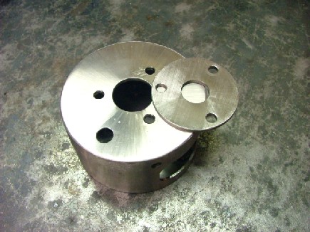
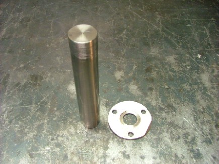
The next step was to drill out the mounting holes for the evap tube base plate and then create the base plate itself. I chose to use a three bolt pattern that would be bolted from the bottom side up. This would allow me to later use stainless safety wire to secure the evap tube bolts in place.
The evap tube base plate was hewn out of 10 gauge 304 plate. I bored a 13/16 hole in the middle of the base plate for the combustion air orifice.
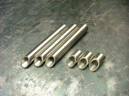
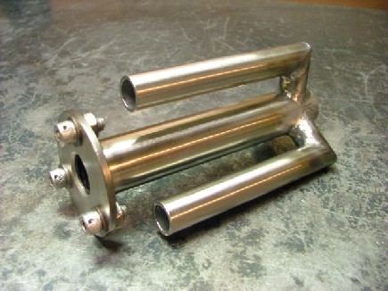
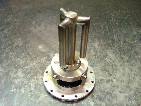
I had ordered an assortment of sanitary stainless tubing from McMaster-Carr for evaporator design experimentation. My proposed evap tube design is based on an educated guess so multiple designs might need to be built and tested to find a successful one. I designed the engine so the combustor end plate would be accessible when the engine is assembled making it easier to try out different designs. Of course I hope that my first design will work without modification :0) My first design will use 1 OD X 0.065 wall sanitary 304 stainless and some 5/8 OD X 0.065 of the same. I call the design the three tree as it has a main trunk that feeds three branches. The cross section area of the 1 tube is about 0.594 sq. in so to promote good fuel vapor flow I needed to size the three evap tubes with approximately the same combined value. I chose the 5/8 because three of them had a cross section of 0.576 sq. in.
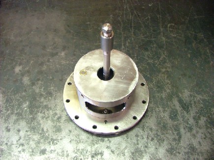
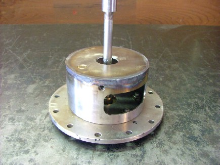
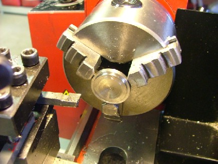
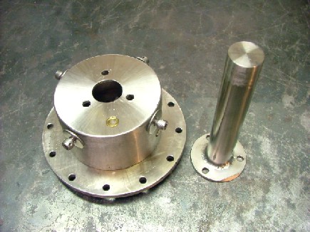
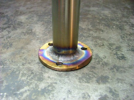
To get started I needed to build an end cap for the main trunk tube. I cut down a 3/4 304L SS threaded pipe cap to use as a round end cap. Using my lathe I fabricated a stepped end cap that fit snugly into the main tube. The cap was then TIG welded into the 1 main tube and then ground. The evap tube base plate was also stepped to accept the 1 main tube. This will help prevent burn through during the welding process.
The main evap tube was welded onto the base plate. I used the belt sander to true the mating surface of the base plate. I then fit checked the base plate to the injector base with the 1/4-20 hardware. Once satisfied I welded the 1/4-20 nuts to the face of the base plate.
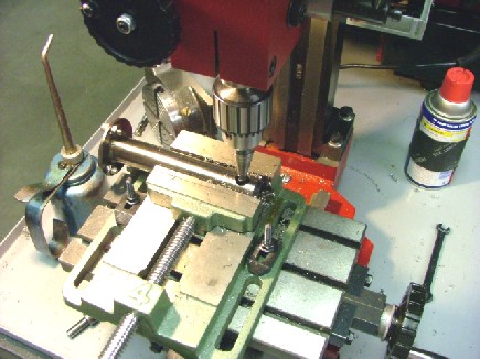
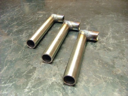
Three 5/8 holes were drilled into the top end of the main evap tube 120 deg. apart. These holes will accommodate the three branch tubes.
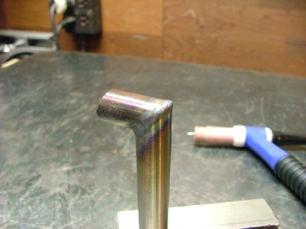
The 5/8 branch tubes could now be cut and welded. By using my band saw I sectioned out the branch tube pieces. I used 45 deg. angles to create the elbow pieces that will be welded into the main tube.
Once again I created a TIG welding challenge for myself. I needed to weld the elbow pieces together without burning a hole in the tubing. A little tricky but I got it done.
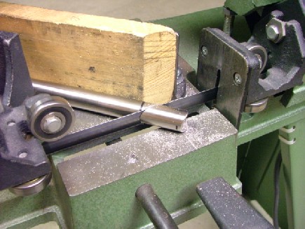
All that was left to do was weld them correctly into the main evap tube. A block of wood was used to space the branch tubes away from the main tube.
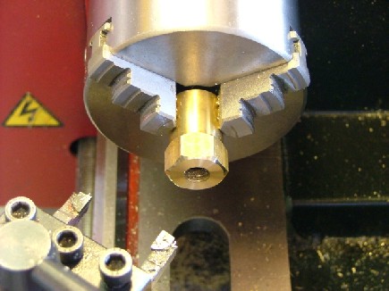
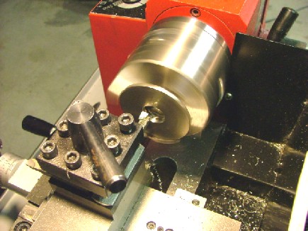
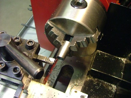
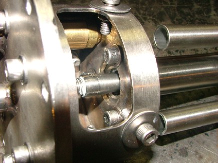
I used a educated guess when I calculated the the length of the evap tube assembly. I figured it would be better to go longer than shorter as I could always shorten the assembly later. Combustor testing will indicate problems with the design which in turn will help me adjust different perimeters of the system. For now this will be a good start. (See final design addendum) To finish the evaporator base/evap tube assembly I need to install the evap tube injector nozzle. The 304L threaded coupling I was going to use with the Hago nozzle was too wide in diameter to allow proper air flow around it. I chose to use the lathe to cut a taper profile to the coupling. I then installed a 10 GPH nozzle to it and attached it to the end plate with a 1/8 304 SS nipple.
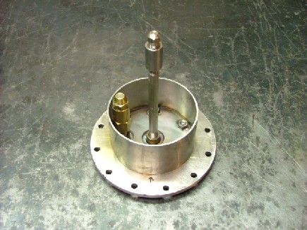
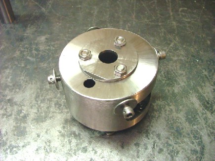
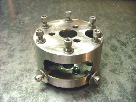
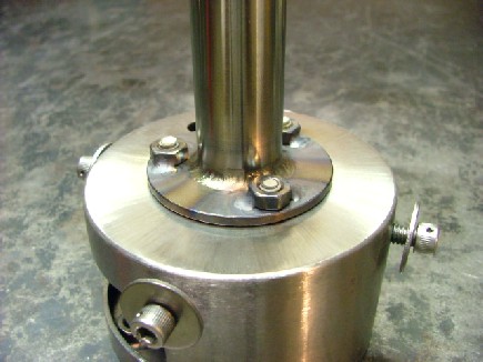
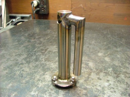
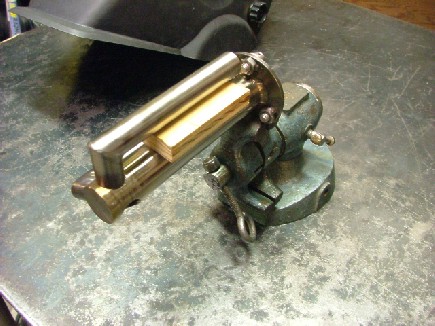
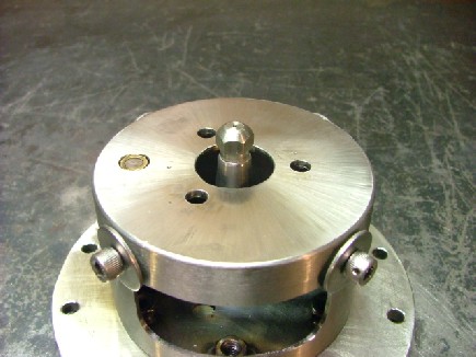
I bolted on the evap tube assembly for a fit check. Notice the wire holes in the cap screws for the safety wire. This will be important as expansion and contraction can cause bolts to loosen over time. The last thing I need would be to spit a bolt at the turbine wheel at full RPM.......
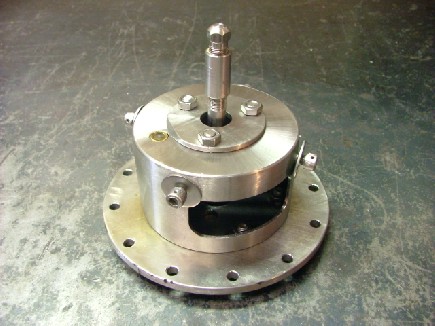
My new fuel delivery system is now complete!!! All I need to do now is fabricate the 4 flame tube and install it on the injector base. Once that is done I can bench test the combustor with a forced air system. Hopefully I will have a successful test and be able to weld the combustor to the elbow in preparation for a real turbine test. I am getting so close I can smell the jet fuel!!! Check back soon for more updates ;0)