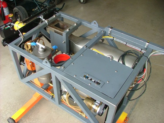
Over the last few years the GR-7 has racked up some notable running time. In fact the engine has over six hours of accumulative running time with approximately 40 gallons of fuel run through the turbine! Thats a significant amount of use for the combustor system, specifically the evaporator. There is bound to be signs of wear and tear due to the hostile environment that exists in the combustor. Having considered this I feel it is a good time for a thorough inspection of the combustor and turbo.
I decided to start off my inspection by removing the VT-50 from the combustor to have a look see at the turbine wheel and bearings.
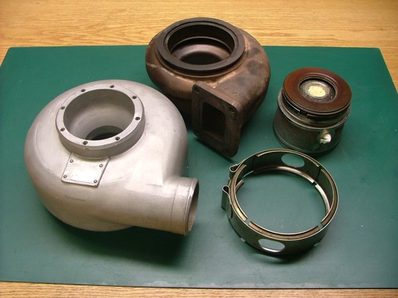
I disassembled the turbo and was very pleased to see nothing abnormal inside. Both the compressor housing and turbine volute were in perfect shape. I also looked into the bearing housing for any signs of heat damage that might of been caused by the shutdown process. Fortunately the cool down cycle seems to be preventing any heat soak back issues as the bearings were clean and bright :0)
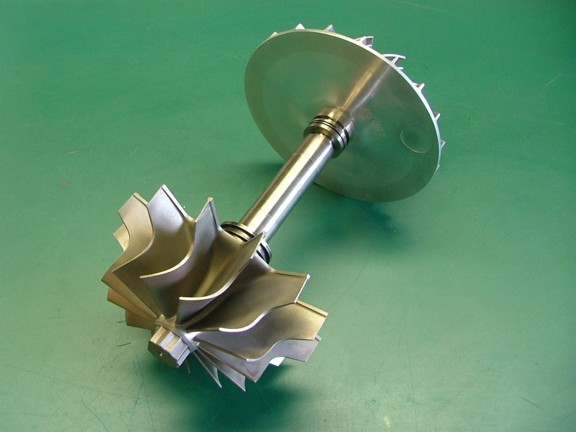
I very carefully inspected the turbine wheel for any heat damage due to the stress testing. Each blade was checked for warping and erosion of which I could not detect any. I even went as far as to clean the carbon deposits off of the turbine to see the metals surface and all checked out A-OK. The bearing surface was also checked for any oil coking which none was detected. I love it when a plan comes together ;0) Since the rotating assembly was already out of the turbo I decided to get the turbines balance checked by a turbo service shop. This would be cheap insurance that the engine is in top shape when it goes back together. To prepare the turbine and compressor wheel for balancing I removed the oil seal rings and cleaned the compressor wheel with a nylon brush and Brakleen (automotive brake cleaner solvent). The ring lands were also cleaned of any carbon build up that might effect the final balance and then scrubbed as well. I carefully packed up the wheels (along with a stock compressor nut and the thrust washer) and sent them off to a turbo servicing facility. With any luck I should get the parts back in a week or two (I hope :oP).
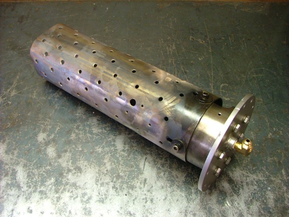
The next step in the GR-7s minor overhaul is to go through the combustor. This hasnt officially been done since the engine was first run in 2007. Luckily this is a fairly simple process thanks to the easy access of the combustor end plate. All I had to do was remove the two fuel lines and twelve combustor bolts for removal of the flame tube assembly.
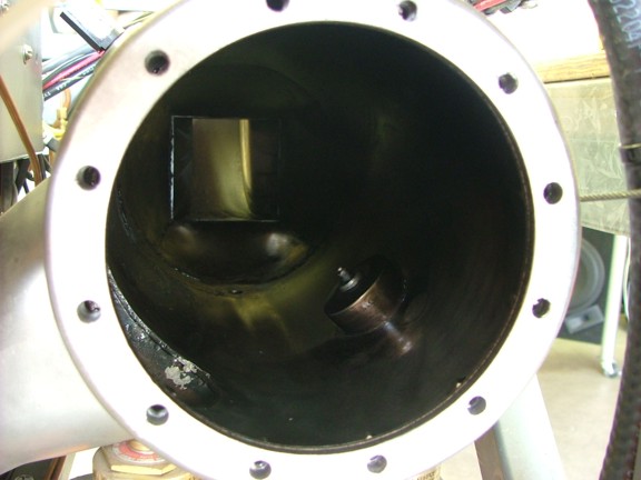
Once the flame tube was out I inspected the combustion chamber for carbon build up or dirt deposits. Nothing really out of the ordinary here so I just wiped out the chamber with a Brakleen soaked rag for good measure.
And now the moment of truth. How well was my combustion liner holding up throughout all of this use. Well, from what I can see it looks good so far. The stainless steel combustion liner (flame tube) was in great shape. No signs of erosion or warping which is fantastic!!! This really is promising news for my combustor design :0)
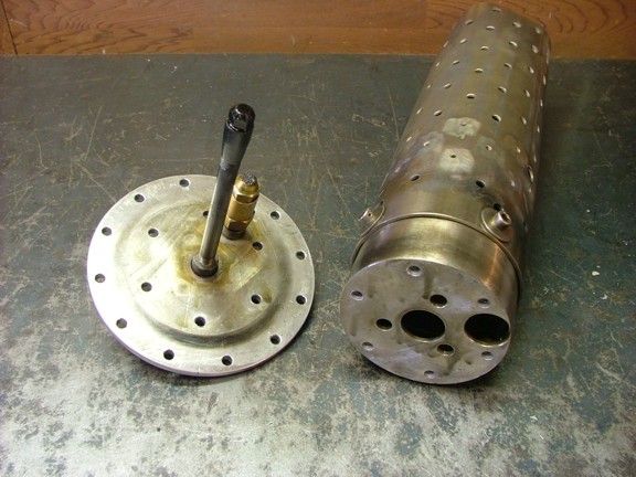
The next step was to remove the combustor end plate from the injector base. This will expose the main and pilot nozzles for inspection. Other than some carbon buildup everything looked normal here as well.
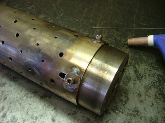
Since the flame tube was operating perfectly as adjusted I decided to weld the alignment washers before disturbing its orientation. The washers were left loose until I was sure the bypass gap was adjusted correctly. Now that I am happy with the alignment I can fix them in place permanently to flame tube.
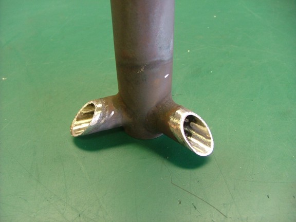
And now for the most important component of the system, the evaporator tubes. I removed the flame tube to expose the evap tubes and was happy to see them in one piece. This single part is what takes the most abuse being that it is exposed to extreme heat and corrosive elements. Surprisingly the tubes held together quite well considering the time they were used :0)
Evaporator tubes are sort of considered as a consumable part on a turbine engine as they eventually wear out. Heat and corrosion usually cause erosion of the metal eventually weakening the walls of the tubes. I designed my evap system with heavy walled tubes specifically for this reason. The thicker the tube, the longer it will take to erode the metal. On commercial engines they use a nickel alloy for evap tube assemblies as the nickel does very well in hot corrosive atmospheres. The only bad part for the DIY builder is that nickel based metals are very expensive. This is why I used 304 stainless steel as a relatively economical alternative. Fortunately the GR-7 will not be asked to endure the same duty cycle of a commercial engine which makes the use of the stainless tubes more practical.
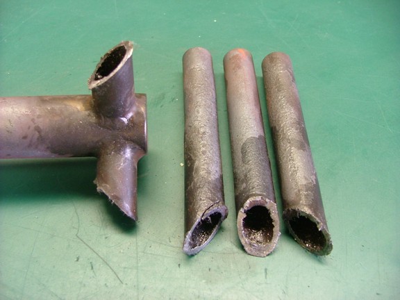
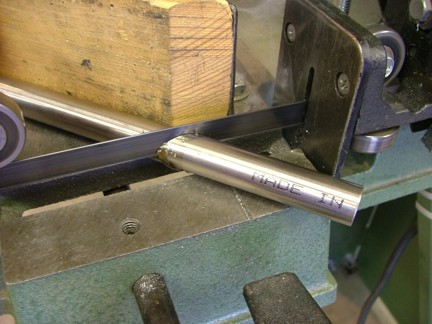
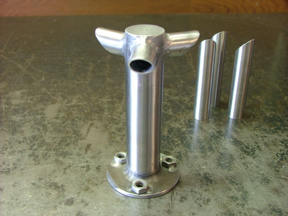
After a close inspection of the tubes I noticed that the middle trunk of the assembly was experiencing too much heat. This was also noticed at the ends of the evap tubes. Slight warping and moderate erosion was also evident at the ends of the tubes. This would indicate that the tubes are too long as I had originally thought they might be. If the tubes are too long it will cause the fuel to start burning inside the tubes causing them to overheat. On the other hand if the tubes are too short they will not evaporate the fuel and consequently dump wet fuel into the combustor. In a proper evap tube system the fuel flow along with the incoming air cools the tubes just enough to keep them at a moderate heat. Its sort of a balancing act requiring the proper length and volume of tubes to work efficiently. In this case the current design works but not as efficiently as I would like it to. Left alone, these tubes would probably last as much as 35 hours longer but that is not what I was really hoping for. For this reason I decided to shorten up the tube assembly and replace the three outer tubes for good measure. The rebuild started by cutting off the outer tubes as seen below. This allowed me to further inspect the tubes by cutting cross sections of the old tubes to measure the erosion of metal. I was relieved to see little loss in metal. However some of the thickness of the tubes was comprised of a carbon layer that had bonded to the metals surface. This carbon layer chewed up my bandsaw blade with ease :o/
To prepare the trunk for new evap tubes I removed the carbon buildup from the metal at the joints. This carbon was extremely hard to remove which may be good in one way. If the carbon layer protects the tubes it could be a good thing making the tubes last longer.
I sand blasted the trunk after cleaning off the carbon deposits. I then marked out where I was going to shorten the trunk.
The trunk was carefully cut and the ends were prepared for welding. It was very important to remove any surface carbon before welding as to not contaminate the weld.
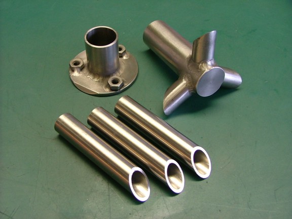
Three new evap tubes were cut out of some 304 stainless tube stock.
All of the parts were cleaned and ready for TIG welding. I prepared the metal by scrubbing it with a Scotch-Brite pad and then washing it with Brakleen solvent.
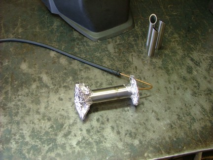
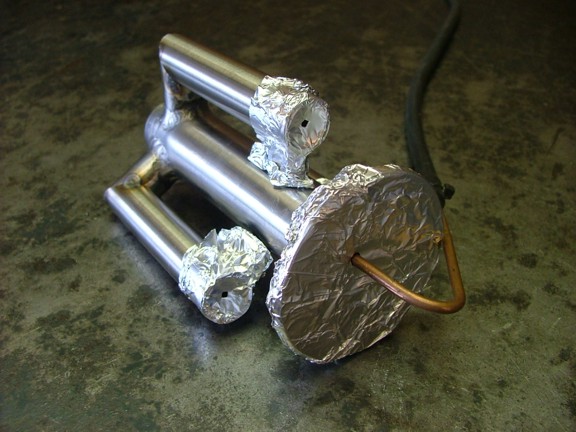
I used a back gas purge stinger to introduce argon into the center of the evap trunk before and during welding. This will eliminate any oxidization of the weld on the inside of the pipe. Aluminum foil is used as end caps to contain the gas in a concentrated amount.
Once the trunk was welded together the bead was ground down and finished with sand paper. You can hardly tell that the trunk was shortened.
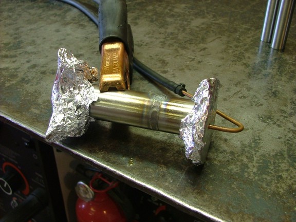
It was now time to add the evap tubes to the tree. I used the same method of back gassing with the argon as before. Notice the holes in the foil at the evap tubes. This ensures that the gas will travel down the evap tubes ensuring the proper purging of air.
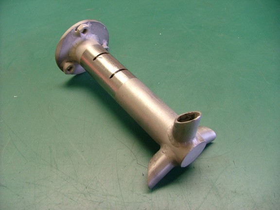
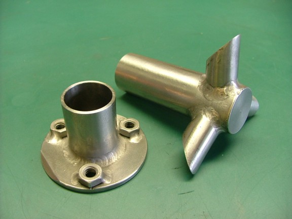
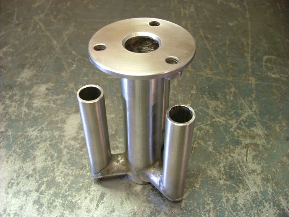
After some careful welding the rebuilt evap tube assembly was complete. This refined evaporator should perform for many hours granted the tubes stay cool. I removed about 2.5 cm of length from the entire assembly resulting in a trunk length of 11.45 cm long and an evap tube length of 7.95 cm.
I also widened the evaporator base orifice to 19.2 mm which should improve tube cooling. The increased air flow will move the fuel along faster and cool the walls of the tubes as it evaporates.
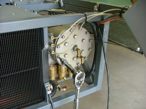
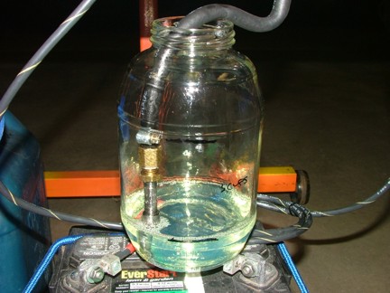
The next item to tackle is the fuel flow issue. During my engine testing session for the GR-7 I encountered a fuel flow problem. The pump I am using is capable of delivering 15 gallons per hour @ 100 PSI. However I am only getting 11 GPH at the nozzle so I needed to figure out what is causing the restriction. To troubleshoot the fuel system I set up a test where I time the fuel flow through the nozzle and then time the fuel flow without the nozzle. I removed the nozzle from the combustor end plate and attached it to the fuel pump of the GR-7 as seen below. I used a home brew graduated cylinder to gauge the time it took for 3 cups of fuel to flow into the jar. With the nozzle attached I was getting about 11.5 GPH and 14.2 GPH without the nozzle. Clearly my nozzle was causing the restriction and not the fuel manifold.
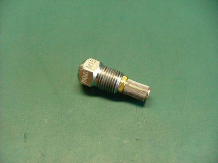
The nozzle I am using for the evaporator is a Hago M15-NS Copper-Nickel alloy misting nozzle (McMaster-Carr Cat# 3178K87). This nozzle is rated for 15 GPH @ 100 PSI. Unfortunately this rating is for water which is less viscous than diesel fuel. Because this is the largest nozzle made of its type I will need to modify it to flow at the rate required for full engine RPM
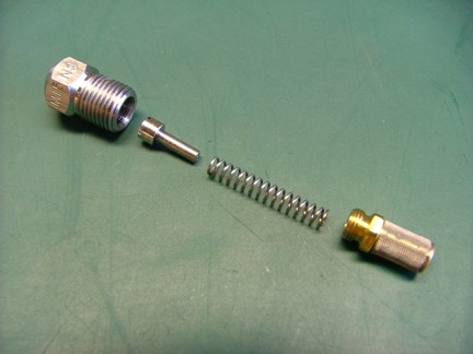
The misting nozzle has a swirling vane insert that swirls the fuel as it leaves the nozzle port. This rotating flow causes the fuel to spray outward as it exits the nozzle. This part of the nozzle is difficult to modify as it is CNC cut to precision tolerances. Any modification to this part would cause the nozzle to spray unevenly. I will leave the inside parts of the nozzle alone.
To increase fuel flow I decided to open up the nozzle end port a little to allow the fuel to leave the nozzle head more easily. The existing nozzle port was about .050 in diameter. I used a carbide drill bit to open the nozzle to about .060
After reassembling the nozzle I tested it for fuel flow once again. I recorded a 18% increase (13.57 GPH) which should help solve my fuel delivery problem. However I wont know if the nozzle will help until I get the engine back together for a test run. The nozzle may act differently under the increased atmospheric pressure of the combustor. Hopefully I will get the turbine back from the turbo shop in the next week or so. I can then assemble the engine and balance the fuel system for full RPM. Join me again next time when I finish the engine in preparation for the GRV-2 jet bike project!!!