 |
|
|
|
|
|
|
|
|
|
|
|
|
|
|
|
 |
|
|
|
 |
|
 |
|
 |
|
|
|
Posted on July 22, 2009
Over 400 hours of work and several thousand dollars went into the research and development of the GR-7 turbojet. Countless weekends and late nights were spent in the garage building and refining this turbo-turbine engine. During this process the GR-7 has seen many phases of construction from concept to creation all the while serving as a priceless learning tool. It is now time to see if all of this hard work will survive the rigorous testing I have planned for the engine.
Up unit now the GR-7 has only been run up to about 80% power in short bursts. This is mainly because I do not have the proper safety equipment to test a large turbine engine. Commercial engines are usually tested inside a reinforced concrete bunker called a test cell. A turbine test cell can protect the operator from shrapnel due to a catastrophic engine failure. I unfortunately do not have a test cell in the garage which means I will need to transport the engine to a remote location for safe testing.
Luckily for me I have access to a remote area in Highland California where the GR-7 can be put through its paces. This location is ideal for turbine testing with 100+ acres of inhabited land. No one to complain about noise or worry about destroying my garage in a fire :o/ Needless to say there was no hesitation in packing up my equipment and heading over to the site for a day of testing.
|
|
|
|
 |
|
|
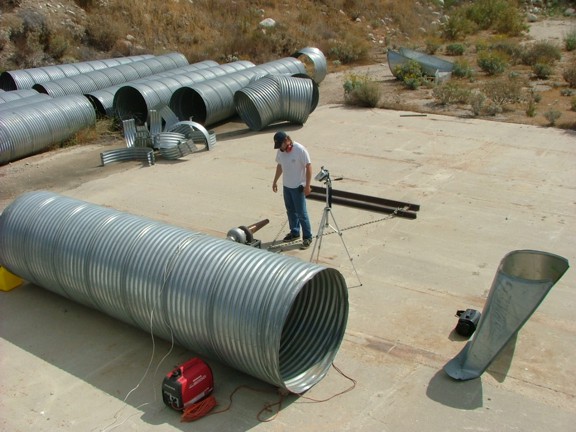
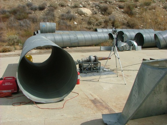
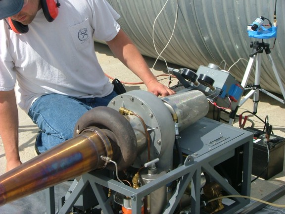
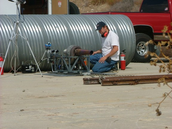
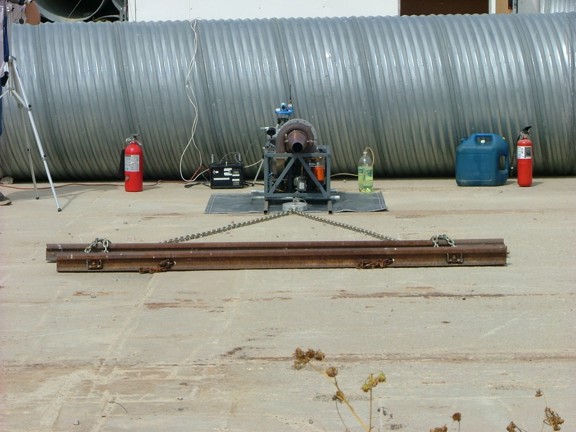
I set up camp at the test site on a concrete pad which is really convenient for my purposes :0) A large steel drainage pipe was used as a safety barrier which was placed between the testing trailer and the engine. The 3/16 thick steel walls of the pipe should help deflect any shrapnel should the engine experience a catastrophic failure (once again, really convenient :0)
|
|
|
|
 |
|
|
|
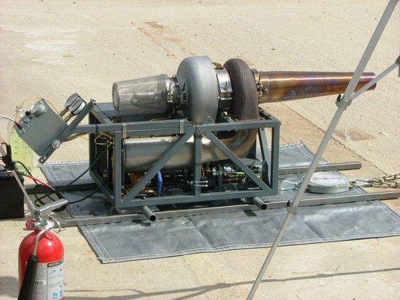
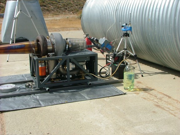
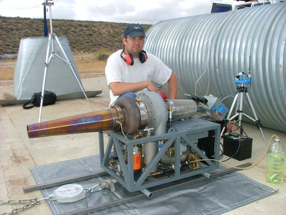
Several static cameras were set up including a wireless remote camera to monitor the engine while it is running. The recorded visual telemetry of the engine will be a very important record of how the engine will perform. You may notice in the photo below that the engine is resting on two steel rails. These rails in combination with rollers below the engine allow the engine frame to slide forward freely. This will allow me to measure the engines static thrust later on.
|
|
|
|
 |
|
|
|
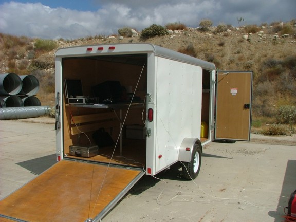
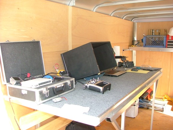
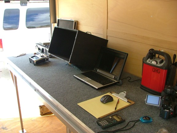
I brought out my enclosed trailer which can double as a workshop. In this case I set up all of my testing equipment inside the trailer and ran my communication cables to the engine on the other side of the barrier.
|
|
|
|
 |
|
|
|
I had brought several testing tools including my laptop (with logging software), RS232 linked multimeter, infrared temperature gun and a 110 lb dynamometer (weight scale). The laptop will be used in conjunction with my multimeter to count the frequency of the tachometer signal. The frequency (in hertz) will be logged on a time stamped record which will be helpful in determining at what speed the engine was running in correlation to the other data recorded at the same time.
I will use the non-contact thermometer to monitor the post-compressor air temperature (T2) and oil temperature when the engine is running. The temp gun is really easy to use as I only have to point at the inlet duct or oil tank to get a pretty accurate reading. The 110 lb weight scale will be used to measure the static thrust of the GR-7. Of course I will have all of the instrumentation of the engine to study which will provide a good part of the data to record.
|
|
|
|
 |
|
|
|
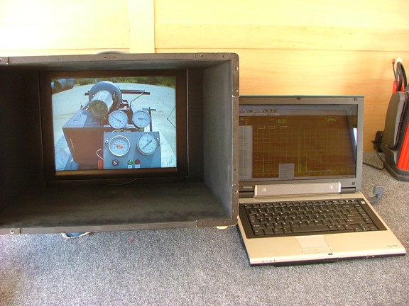
A really helpful tool that I brought was my wireless remote camera system which I frequently use in my aerial video productions. This wireless video system will allow me to remotely view the engine running real-time much like a professional testing facility would have. I have a 13 LCD portable monitor which shows incredible detail of the remote video signal.
|
|
|
|
 |
|
|
|
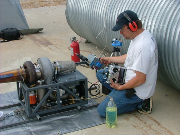
I decided to actuate the throttle of the GR-7 with a remote control system that would normally be used in a RC model airplane. I used my Futaba 14MZ transmitter to send a 2.4 GHz spread spectrum signal to a receiver mounted on the GR-7. The receiver in turn controls a heavy duty digital servo that actuates the throttle arm. This system works great and eliminates any external force on the engine frame which can contaminate the static thrust data.
|
|
|
|
 |
|
|
|
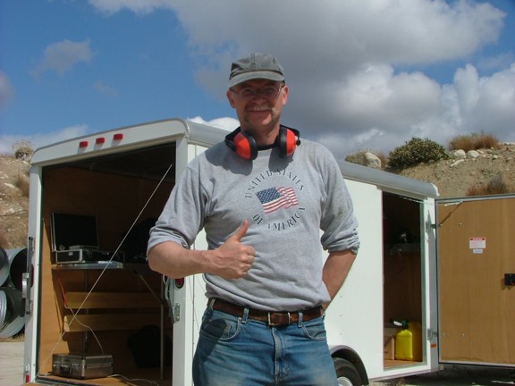
Helping me on test day was my good friend Andreas Blaser. I have been flying model airplanes with Andreas for several years now and he was kind enough to drive out to help me set up and film the testing session. It was also a good idea to have someone around for safety reasons. Thanks again for the help Andreas!!!
|
|
|
|
 |
|
|
|
To prepare for the first test I decided to warm up the GR-7 a bit. I fired up the engine for a few minutes allowing it to reach full operating temperature. I shut down the engine and readied the testing equipment in the trailer. So far so good!!!
|
|
|
|
 |
|
|
|
One of the first tests that I performed was a prolonged full power test. This test I had not yet attempted at my home as I was not sure the engine would be stable enough. After recording an air temperature of 76* F I started up the GR-7 to proceed with the test. I throttled up the engine to 100% for several minutes while carefully watching the Exhaust Gas Temperature-EGT (also referred to in the gas turbine industry as the Turbine Outlet Temperature-TOT). The engine spooled up to full speed in only a few seconds emitting an amazing sound very similar to a full sized jet taking off :o))))))).
Initially the engine topped out at 62,000 RPM with an EGT of about 1100* F. This RPM reading was about 4,000 RPM slower than I expected of the engine. I shut down the engine and let it cool for several minutes while I checked over the throttle linkage. I had hoped by advancing the throttle a little more I could achieve my top RPM of 66,000. After tinkering with the linkage I ran the engine again to no avail. It was only going to give me 62,000 RPM.
|
|
|
|
 |
|
|
|
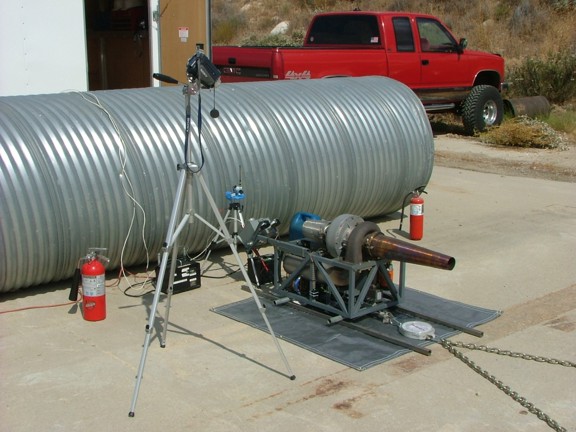
At this point I decided to continue on with a very important test of the day, the stress test. The test is performed while a 68mm diameter choke is installed on the jet pipe end. This choke increases the engines back pressure and thus increases the EGT. If the engine can handle the increased temperature at 100% power it will be more likely to survive any minor fluctuations in temperature when in use on a vehicle.
I attached the choke to the jet pipe with a 8-32 screw and proceeded to fire up the engine. Right away the engines EGT was 50* higher than without the choke, a sure sign that it was working. Once I returned to the testing trailer I slowly ramped up the throttle taking note of the EGT as I went along. The engine maintained 1010* F up until about 50K RPM. It then ramped up sharply all the way to 1250* at 61K !!! I ran the engine for a minute under these conditions before spooling it down to cool off a bit.
1250* F is arguably one of the highest TOT temps you should subject a turbo to under high speed. This is because the Turbine Inlet Temperature (TIT) feeding into the turbine blades will be much higher than the TOT. Turbo turbine blades can warp and eventually fail under these conditions. However some turbos can handle up to 1500* F TOT without issue!!! Overall it is better to be safe than sorry and keep the EGTs below 1200* F for DIY engine purposes (IMO).
|
|
|
|
 |
|
|
|
Once the engine cooled down a bit I removed the choke to get a static thrust reading. The dynamometer scale had already been attached to the engine and anchored to a set of steel tracks as seen below.
|
|
|
|
 |
|
|
|
The thrust test was easy enough to perform. I spooled up the engine and took some readings off of the dynamometer scale at different RPM. I was somewhat disappointed to read that the full static thrust reading was 47 pounds. This is pretty far from the 65+ pounds of thrust I had originally set out to produce when I started this project :0( However I still had a problem to fix before I could call this reading accurate.
The low full RPM of 62K was bothering me and I wanted to find out if this had anything to do with the low thrust readings. I decided to find out if fuel delivery was the issue by measuring the fuel flow to the combustor at full power. This would tell me if the engine is getting proper flow or if there is a bottleneck in the system somewhere.
|
|
|
|
 |
|
|
|
I devised a graduated cylinder out of a 2 liter bottle with hash marks on the side for reference. I used 1 cup as a unit of measure for my hash marks (in a 2 liter bottle of course :0P). The engine was run at idle and at full power to get a bench mark reading of fuel usage. A video camera was used as a record of how long it took to burn fuel from one mark to the next.
See some of the testing video footage here!!!
|
|
|
|
 |
|
|
|
Initially the readings were lower than I had calculated. At idle the fuel usage was 4 gallons per hour @ 31,000 RPM (which was normal). However the full throttle usage was only 11 GPH @ 62,000 RPM. This was the problem as my calculated fuel flow for the engine to achieve full RPM is +/-13 GPH. More than likely there is a restriction in the fuel system somewhere but somewhat difficult to sort out in the field.
I decided to field fix the fuel flow problem by cranking up the fuel pressure on the fuel pump. Unfortunately the fuel gauge I had installed only read up to 100 PSI and I was already at 95 PSI. This meant I had to feel out what pressure to set the fuel regulator at to achieve 13 GPH at the combustor. With some trial and error I was able to get the proper flow to the combustor for full power. However the current drain from the over exerted fuel pump was evident. This would eventually need to be solved by fixing the plumbing of the fuel system.
|
|
|
|
 |
|
|
|
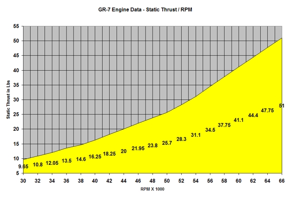
I recharged the engine battery and fired up the engine for another thrust test to see if the improved fuel flow would help a bit. I spooled up the engine slowly watching the video telemetry very carefully. Once the engine approached 65K I knew the improved fuel delivery was helping. The engine reached 66,000 RPM and a thrust reading of 51 pounds was recorded which was a good improvement :0) Still not quite 65 pounds but respectable anyway.
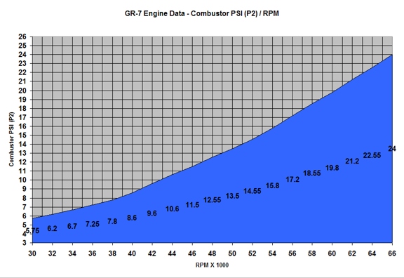
The higher RPM did increase the EGT from 1100* to 1200* F which pretty much guarantees the upper limitation of the turbine/combustor configuration. More fuel flow would just push the engine into overheating. So that is that, the GR-7 produces 51 pounds of thrust at 85* F @ 29.8 inHg - 1722 AMSL. I spent some time while the engine was running to slowly go through the throttle range to document the thrust curve (which can be seen below).
Using the recorded video of the days events I was able to chart out combustor pressure as well as EGT in reference to RPM. However the PSI gauge I was using at the time of the test was seriously faulty :o/. In fact it was reading about half of what it should be. Luckily with some help from a fellow turbine enthusiast John Wallis I was able to figure this problem out before I published incorrect data. Thanks again John!!!!!!!!!! A proper gauge was fitted to the engine later and new P2 tests were conducted at the shop to create an accurate graph (seen below).
|
|
|
|
 |
|
|
|
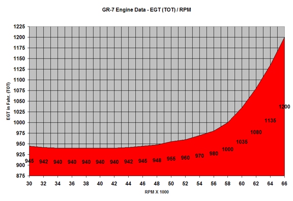
The GR-7 has a slightly different EGT curve than the original GR-1 engine. It spikes heavily at the end of the throttle range whereas the GR-1 sort of plateaus out at 1020* F. This could be caused by a number of things but I think that it is most likely a result of high gas pressure at the jet nozzle (where the EGT thermocouple is). This would indicate (IMO) that the jet nozzle is sized just small enough to maximize thrust and not overheat the engine.
It is actually really amazing that the GR-7 can stay cool burning over 1,775,000 BTUs an hour (29,583 BTUs a minute) of energy! Thats enough fuel to heat a 50,000+ square foot building in the winter or run a 260 hp diesel engine at full throttle for one hour!!!!
|
|
|
|
 |
|
|
|
The thrust curve looks fairly similar to the GR-1 engine except that the GR-7 produces almost twice the thrust in relation to inducer size over the GR-1 engine! The GR-7 flows about 1.33 lbs/sec of air through the engine at full throttle which is equivalent to about 18 cubic feet per second. That is equivalent to emptying a 10,000 gallon swimming pool of air in 1.44 minutes!!! The jet nozzle creates a gas flow of about 1300 feet per second. Thats 118 MPH faster than the speed of sound!!!
|
|
|
|
 |
|
|
|
The GR-7 has not disappointed me in that it performed well in several categories. Not achieving my target thrust of 65 pounds was not so bad considering the engine ran very well for long periods of time. I think that the thrust rating can be augmented later with an afterburner should I choose to build one. I should be able to add 20+ pounds of thrust from a well built AB. We will see ;o)
|
|
|
|
 |
|
|
|
My work is not done yet as I still need to tear down the engine to inspect the turbo and combustor. I also need to rework the fuel delivery plumbing so I can reduce the demand on the fuel pump. Once that is complete I can call the engine finished. Then I can start the GRV-2 jet bike project and put this engine to work!!!!
Please visit RCDON.COM again for the continuation of the GR-7 turbojet engine project!!!
Don R. Giandomenico
|
|
|
|
|
|
|
|
|
|