 |
|
|
|
|
|
|
|
|
|
|
|
|
|
|
|
|
 |
|
|
 |
|
 |
|
 |
|
|
|
Posted on June 26, 2009
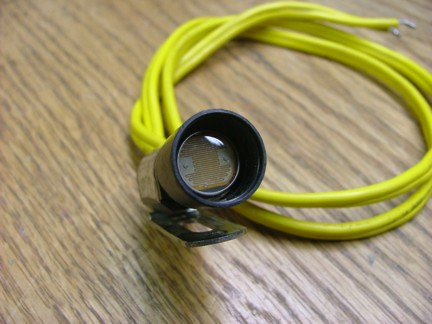
At this point the GR-7s ECU is almost ready for its maiden run in the engine frame. Hundreds of hours of work has lead me to this point with only a few details left to work out. The photoresistor sensor that helped me build the fuel delivery control board was ready for its final install. The sensor that I am using is a cadmium sulfide flame sensor (photoresistor) unit out of a Honeywell furnace controller unit (Cat #C554A1463 + #130367). This sensor lends itself quite well to my project as it fits into the combustor sight glass holder with little modification.
|
|
|
 |
|
|
 |
|
|
|
The photoresistor cell unit comes in two pieces; the base socket and the cadmium sulfide flame sensor cell.
|
|
|
 |
|
|
|
To get the sensor cell to fit into the sight glass holder I needed to lightly sand down the sides of the cell. The sensor cell now fits into the holder nice and snug, a perfect fit!!!
|
|
|
 |
|
|
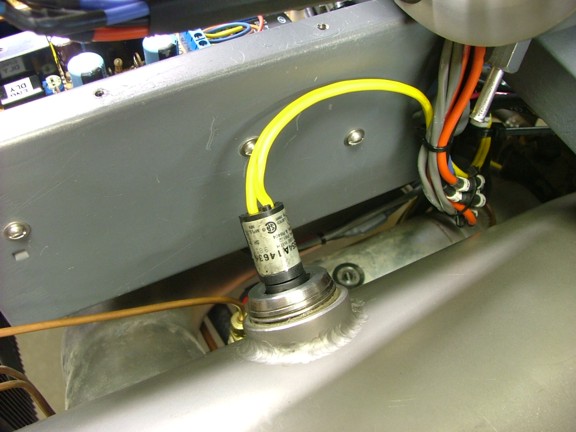
I had already set up the FDC board to work with this sensor so the only thing left to do was land the wires and wait for the first live engine test.
|
|
|
 |
|
|
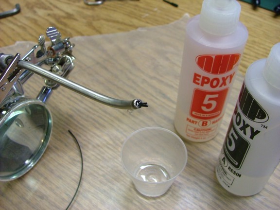
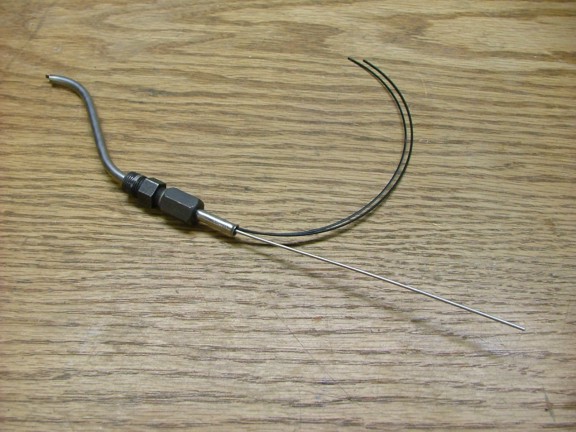
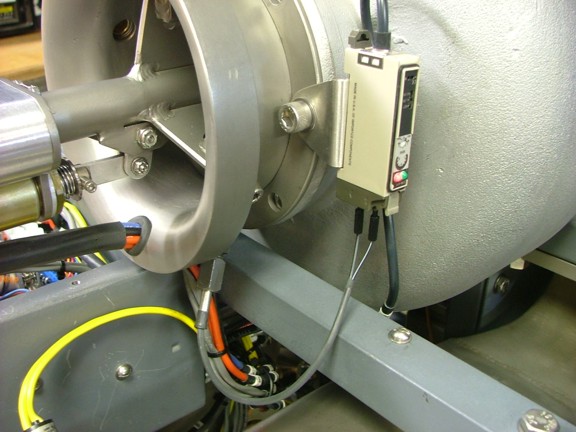
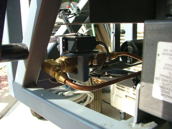
The Omron fiber optic sensor cables for the tachometer needed to be installed at this point. I had already precut the fiber cables to the approximate length for the sensor tube earlier. The next step would be to use epoxy resin to hold the end of the fibers at the compressor nut side of the tube.
|
|
|
 |
|
|
I used some 5 minute hobby epoxy to pot in the fiber cables at the very end of the sensor tube as seen below. This epoxy can also be removed later if needed by heating up the tube with a torch however the fibers most likely not survive the heat. This is why I want to get the alignment perfect the first time.
|
|
|
 |
|
|
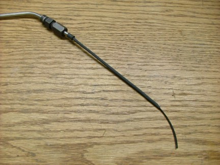
While the epoxy is curing I decided to add a stiffening wire to the fibers as they exit the sensor tube. This wire will help prevent inadvertent damage to the fiber cables due to bending them to tightly. I used a piece of stainless safety wire which was inserted into the sensor tube all the way to the epoxy.
|
|
|
 |
|
|
I used some heat shrink tubing to hold the fibers to the support wire as seen below.
|
|
|
 |
|
|
|
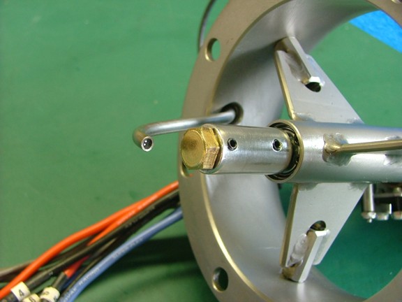
The last step was to trim the end of the fibers flush with the end of the sensor tube. I did this with a fine grit sanding drum on my Dremel tool. Notice that the sensor fibers are located perpendicular to the shaft of the starter. This alignment of the fibers will help reflect the sensor light off of the compressor nut more efficiently than in line with the shaft.
|
|
|
 |
|
|
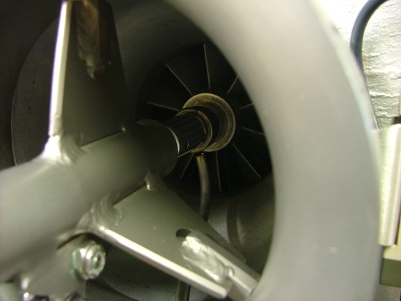
At this point I was able to fire up the Omron E3X-A11 sensor module and dial in the sensor tube location. By putting the module in set mode I was able to see what angle the fibers can best pick up the compressor nuts light and dark sides. Notice the red dot at the end of the fiber tube, this is the light source that the Omron sensor produces to be sensed by the second fiber in the tube.
|
|
|
 |
|
|
I fine tuned the sensitivity of the sensor and checked my output to the ECUs MCR board. All is looking good and now I am ready for a test run!!!
|
|
|
 |
|
|
Having everything ready for my first ECU controlled engine run was a big milestone of the project. However I was a bit nervous allowing the ECU to control the start up sequence for the first time being that I was not exactly sure if it would work as I had envisioned. One of the features that I needed to bypass before I could start the engine was the combustor pressure switch. The combustor pressure switch is what tells the ECU that the engine is running and needed to be set exactly at idle PSI before it is connected to the ECU.
To help set up the ECU and pressure switch I needed a bypass switch to fool the ECU that the engine is running. This will allow me to manually control the run cycle without using the unadjusted pressure switch. Once the engine is running I can set the switch and reconnect it back to the ECU.
|
|
|
 |
|
|
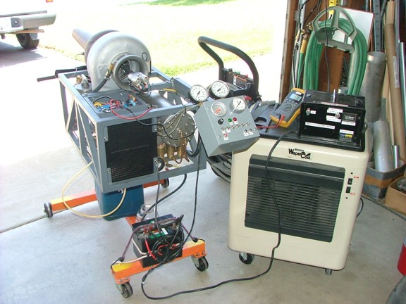
I hooked up a remote bypass switch to the ECU and also hooked up a continuity meter to the combustor pressure switch so the sensitivity could be set when the engine is running. All that was left now was to flip the switch :0P
|
|
|
 |
|
|
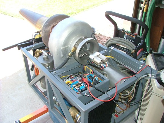
With a knot in my stomach I dawned my safety glasses and ear protection and flipped the run switch. The oil pressure ramped up to 50 PSI and the starter shaft engaged. I could hear the speed controllers beep indicating that they were armed and ready. I flipped the start switch and the starter motors spooled up the big turbo to 2,600 RPM. After a few seconds the pilot burner lit up with a slight rumbling sound illuminating the photo indicator LED on the MCR board.
The RPM switch sensed that the turbo was spinning fast enough and illuminated the RPM indicator lamp. The ECU was now waiting for the minimum burn timer to indicate that the pilot burner has run long enough. With a click I heard the starter motors start to ramp up and the familiar howl of the main burner kick in. I watched the exhaust gas temperature (EGT) ramp up while the engine reached the full start speed of 24,000 RPMs.
I noticed that I needed to apply throttle to get the engine to self sustain so I rolled up the throttle lever to reach idle. I then promptly hit the combustor pressure bypass switch which immediately retracted the starter shaft. The engine was running!!!
|
|
|
 |
|
|
I now had the job of adjusting the combustor pressure switch to the idle pressure setting of about 5 PSI. Once that was completed I shut down the engine to attempt a full auto start with the pressure switch attached. Once again the engine cycled through the start sequence nicely but I still had to apply throttle to get the engine to idle RPM. I was kind of hoping for the idle fuel flow to be the same as the starting flow but in reality the two could not be the same.
When I attempted to start the engine at the fuel flow needed for sustained idle I experienced too much unburned fuel being blown past the turbine wheel. This condition would not be very good for the engine so I needed to slowly ramp up the fuel as the engine was spooling up. To make this process happen automatically I decided to fall back on my remote control roots and add a throttle advance servo to the throttle assembly.
|
|
|
 |
|
|
|
Luckily the SMC board had three servo outputs to use of which two were currently used for the electronic speed controllers. The third output was a spare and could be used to drive a throttle advance servo which would slowly ramp up the throttle valve in sync with the starter motors. To do this I would need to build a servo bracket into the throttle assembly and fabricate a cam system to roll on the throttle as needed.
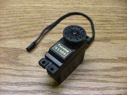
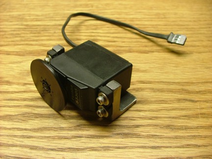
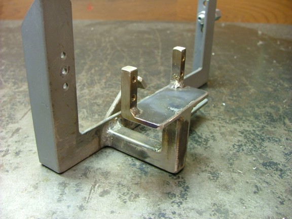
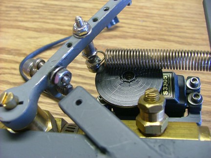
I needed a strong servo for the throttle advance so I robbed one from my RC stock, a Futaba S3305 metal gear servo. Once I had the servo in hand I started to build a metal bracket that would cradle the servo as seen below.
|
|
|
 |
|
|
|
 |
|
|
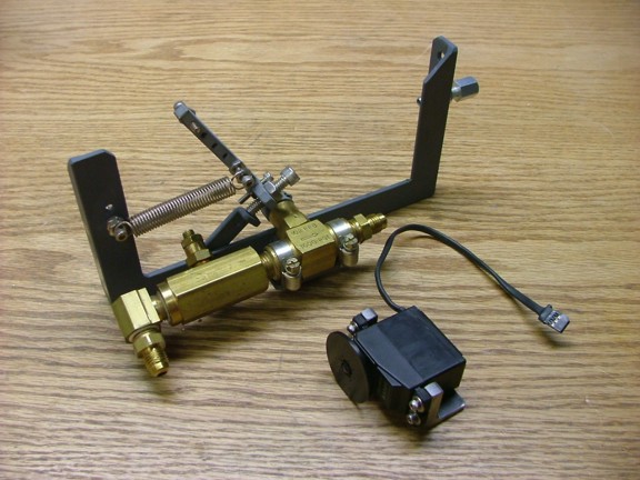
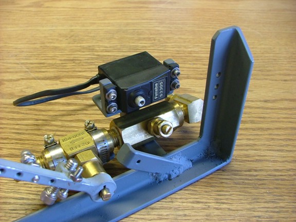
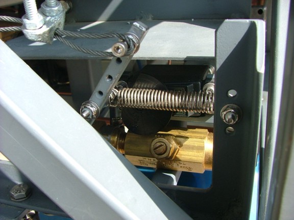
I welded some 1/2 square tubing to hold the servo bracket to the throttle valve assembly as seen below.
|
|
|
 |
|
|
 |
|
|
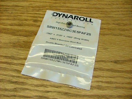
To control the advancement of the throttle arm I decided to use a roller cam system like you would see in a car engine. I purchased a ball bearing roller to be used as the cam follower which will greatly reduce friction.
|
|
|
 |
|
|
|
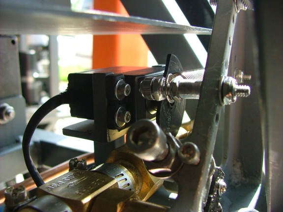
The bearing I chose has a shouldered inner race that holds it off of the sides of the support screw as seen below.
|
|
|
 |
|
|
|
I replaced the return spring and I was in business!!!
|
|
|
 |
|
|
 |
|
|
|
All that was left now was to attach the servo to the SMC board with an servo extension wire and trim the cam wheel. After playing with a few different profiles I was able to find a perfect fit for the timing of the start sequence.
|
|
|
 |
|
|
 |
|
|
After several starts I was able to fine tune the throttle valve trim to start every time with minimal hot spikes on the EGT meter.
|
|
|
 |
|
|
Now that the ECU was performing just as I had envisioned it I could fine tune other issues that needed to be addressed before the big test day soon to come. One of these issues is the oil consumption of the VT-50 turbo. The longer and longer I had run the engine I had noticed that the oil pressure would drop from 50 PSI to as low as 20 PSI depending on the ambient temperature that day. This is caused by the engine oil thinning out under the extreme temperature of the turbine shaft. Ultimately I did not want the oil to ever drop below 25 PSI so this needed to be adjusted.
To modify the oil pump to deliver more of a consistent pressure I decided to lower my overall starting pressure of 50 PSI to more of a higher flowing 35 PSI. This was done by changing the belt ratio of the pump system pulleys as seen below.
|
|
|
 |
|
|
The new 1:2 pulley ratio along with reducing the regulator to max out at 35 PSI helped promote a more even oil pressure during the different heat cycles of the engine. Originally the I projected that the VT-50 would use 1 gallon of oil per minute but actually (depending on the temp of the oil) can use as much as 1.6 GPM @ 35 PSI. Overall this is a good compromise for engine longevity.
|
|
|
 |
|
|
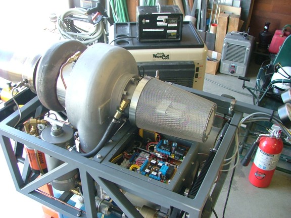
Another issue that I wanted to address was the oil vapor recovery filter located on the bellmouth. This filter helps keep dirt from entering the oil tank breather but still allows oil vapor and turbo bearing blow by to be recycled into the intake of the engine (eliminating the famous smoking oil tank). The filter is clogging up with oil vapor causing excessive back pressure in the system.
|
|
|
 |
|
|
On my GR-5A engine I used an oversized automotive fuel filter for the Oil Vent Recovery (OVR) filter (sorry, but I love acronyms. Just had to throw one more in ;0P). The smaller fuel filter I chose for the GR-7 just wasnt cutting it so I upgraded to a longer filter that should hopefully prove to breath better than the previous one.
|
|
|
 |
|
|
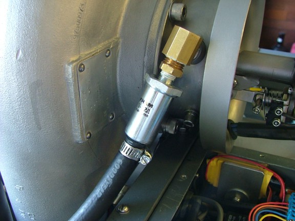
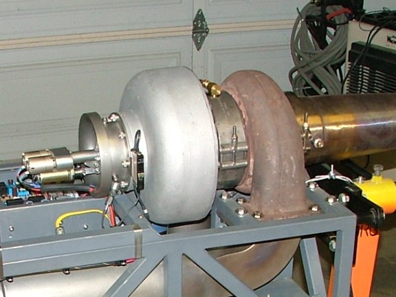
Oh BTW, for those astute readers that might have noticed that I had changed the original clamshell style clamp that holds the VT-50 together to a stainless band clamp. Well, I had found this newer style of clamp online and just had to use it on the project because it was .............................................
............................ shiny stainless steel of course :o)
|
|
|
 |
|
|
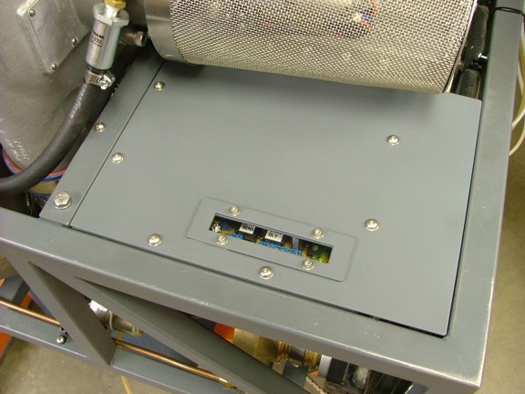
Another detail that I really wanted to add to the ECU box was an observation window for the indicator LEDs. I cut a window into the ECU box cover that is directly over the LEDs on the MCR board. This little modification will save the headache of removing the cover to inspect the proper sequencing of the ECU. Overall it will save time troubleshooting problems should they arise in the field (especially when there is a crowd of looky-loos watching you frantically work to fix your contraption :oP).
|
|
|
 |
|
|
 |
|
|
See the new ECU run the GR-7 engine here !!!
I am sooooo close to the official test day and finding out how well the GR-7 will handle sustained full power runs. I will also be able to report my official thrust readings as well as the overall RPMs the engine will be capable of.
Please return for the continuation of the GR-7 project, coming soon!!!!
Don R. Giandomenico
|
|
|
|
|
|
|
|
|