|
|
|
|
|
|
|
|
|
|
|
|
|
|
|
|
|
 |
|
|
|
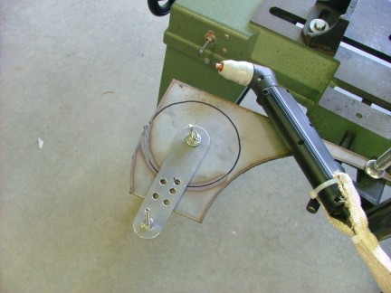
To cut out the end plates I used my circle cutting jig and plasma cutter. I attached the cutting jig to the plate with a 1/4-20 bolt and zapped out two identical end plates for the tank.
|
|
|
|
 |
|
 |
|
|
The assembly was ready to be TIG welded together so I set up the welder and burned on the end plates.
|
|
|
|
 |
|
|
|
 |
|
|
|
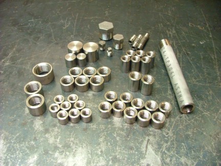
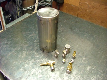
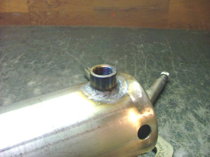
To connect the various hoses and tubes to the oil tank I would need to weld threaded fittings into the body of the tank. To do this I had purchased some 304L stainless steel half-couplings from McMaster-Carr Supply. The couplings can easily be welded into the sides of the tank wherever they are needed.
|
|
|
|
 |
|
|
|
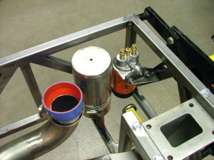
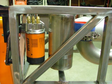
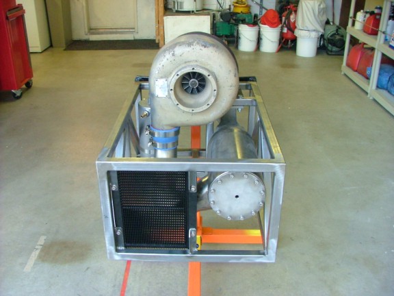
Before I could decide where I to install the tank fittings I needed to mount the tank into the engine frame. With the tank mounted I would be able to determine where the tank fittings would not interfere with other engine components. To do this I fabricated a tank cradle that I welded to the engine frame. The oil tank was then fastened to the tank cradle with a 4 hose clamp. I adopted this mounting idea from the GR-1 oil tank design.
|
|
|
|
 |
|
|
|
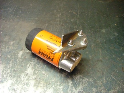
I decided to install the oil filter assembly while I was at it. I fabricated a bracket for the remote oil filter receptacle an welded it to one of the rear frame members.
|
|
|
|
 |
|
 |
|
|
 |
|
|
|
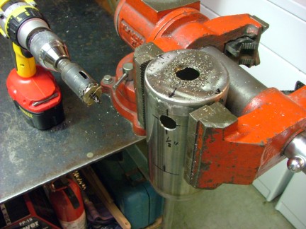
I now had the information I needed to properly place the threaded fittings into the oil tank body. All I had to do now was drill out the holes and weld them in place.
|
|
|
|
 |
|
 |
|
|
 |
|
|
|
This project provided good welding practice for me especially before I tackle the evaporator assembly. I am definitely having too much fun with the Tigmate welder :0)
|
|
|
|
 |
|
|
|
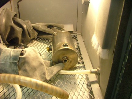
After completing the welding process I decided to bead blast the tank. I prepared the metal by sand blasting it completely. Sand blasting the metal removes all of the surface impurities, preparing it for the bead blasting process. Once cleaned, I loaded up the blasting cabinet and went to work.
|
|
|
|
 |
|
|
|
The finished oil tank looks good! The bead basting process really gives the metal a professional look.
|
|
|
|
 |
|
|
|
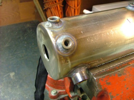
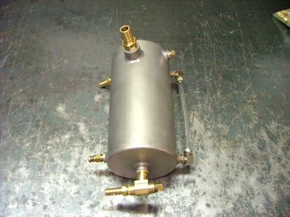
The final tank configuration will hold about 1.7 quarts of oil. That should be plenty of reserve to allow for level fluctuations and air bubble separation. I had added a couple extra threaded fittings to the tank to incorporate a sight tube. The sight tube is helpful in measuring the oil level in the tank while the engine is running. I installed the sight tube and other fittings on the tank in preparation for installation.
|
|
|
|
 |
|
|
|
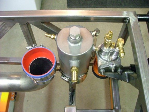
The completed tank was strapped back into the engine frame to make sure all of the fittings would clear the combustor and oil filter.
|
|
|
|
 |
|
|
|
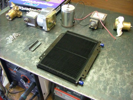
The next step was to install the oil cooler. By mounting the oil cooler I can properly align the pump motor/cooling fan behind it. The fan will pull cool air through the oil cooler during operation. For my oil cooler I planned on using a B&M Supercooler oil cooler that I got from Summit Racing a few months back. The B&M cooler features an efficient stacked aluminum plate design that resists damage unlike a conventional tube & fin design. The cooler is also very light so that is a plus.
|
|
|
|
 |
|
|
|
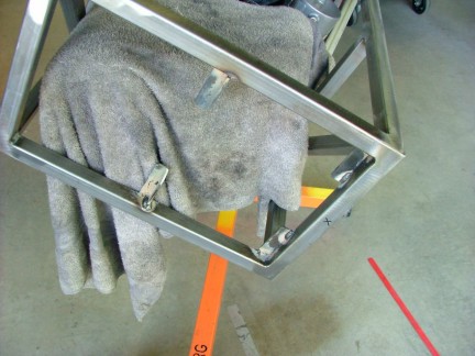
I had mapped out a location to install the cooler in the front of the engine frame. This would allow natural airflow to help cool the oil assuming the engine is moving forward. I welded mounting brackets to the front of the engine frame and drilled them out to match the cooler mounting holes. Notice the wet shop towel over the combustor, protecting it from weld splatter.
|
|
|
|
 |
|
|
|
The oil cooler was now in an optimum location for cooling. The cooling fan/pump motor can now be centered behind the cooler.
|
|
|
|
 |
|
|
|
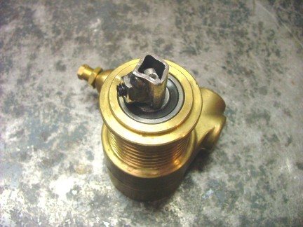
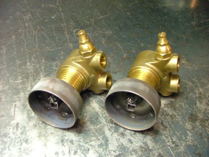
It was now time to set up the oil pump assembly. A while back I had acquired a couple Rotoflow/Procon (Fluid-O-Tech) rotary vane pumps for use as oil pumps on my projects. These little jewels have proven to be the best setup for my DIY turbine engines. The robust engineering and built-in pressure relief valve have made these pumps very useful to me. However there is one drawback to using these pumps, the input shaft is not round so a custom adaptor is needed.
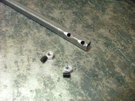
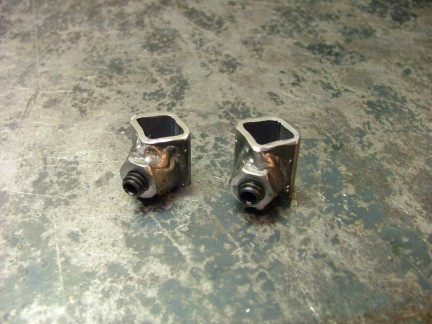
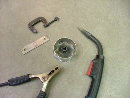
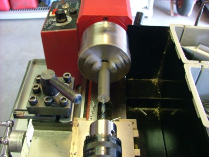
I had devised a way to make a cheap shaft adaptor for these pumps during the GR-1 project. At The time I had not documented it so I though I would share it now. I start out by drilling a 1/4 hole diagonally in a 1/2 X 0.060 square tube. This is where I weld a 1/4-20 nut to the hole for use with an Allen set screw. Once welded, the square tube is sectioned up to size and fitted to the flat pump shaft. The square profile needs to be squashed a bit to fit the pump shaft correctly. This can easily be done with a bench vise.
|
|
|
|
 |
|
 |
|
|
 |
|
|
|
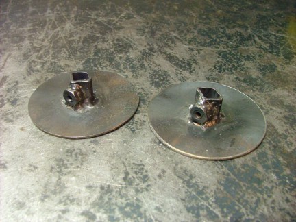
I can now weld on a pulley back plate to the shaft adaptor. I use 16 gauge steel to make the back plate. I tack weld the plate in place while on the pump to guarantee proper alignment. I then remove the plate and weld around the shaft adaptor.
|
|
|
|
 |
|
|
|
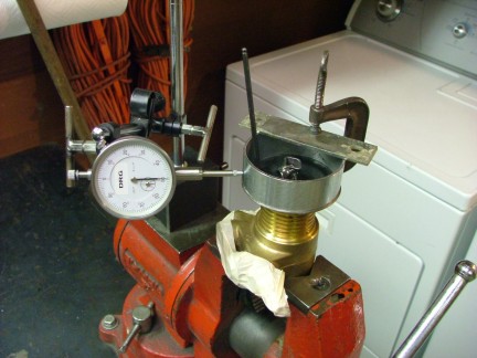
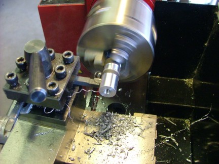
Once the back plate is fitted I can weld on the 2-1/2 EMT pulley face. The pulley face is centered on the pump shafts axis by using a dial indicator. The face is then tack welded in place and removed from the pump for final welding.
|
|
|
|
 |
|
|
|
 |
|
|
|
I reinstall the pulley on the pump shaft so I can use my belt sander to clean up the outer edge. By diagonally sanding the pulley face, I can remove any part of the back plate that sticks out past the pulley face. During this build I fabricated two pulleys, one for the GR-7 and one for future use.
|
|
|
|
 |
|
|
|
The pulley for the pump drive motor was the next task at hand. Before I could make the pulley I needed to know what pulley ratio would be best for the motor/pump combination. If the pump turns too slow it will not feed the turbos bearings. If it turns too fast it will waste on board electrical power. The Rotoflow pump I am using (Made by Fluid-O-Tech Italy Cat# PO204) must turn around 1,350 RPM to sufficiently feed the VT-50 turbo. I estimate the needed flow to be around 1 GPM (Gallon Per Minute) @ 50 PSI.
The DC motor I am using turns around 5,400 RPM so a 4:1 ratio must be used to achieve a pump speed of 1,350 RPM (See addendum). Armed with this information I fired up the lathe and got to work. I started off by boring a piece of aluminum rod to fit the 8 mm shaft of the drive motor.
|
|
|
|
 |
|
|
|
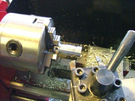
A set screw thread and fan screw thread were tapped into to the pulley hub. I then cut the beveled profile into the pulley face. This bevel will help the drive belt track correctly on the pulley face.
|
|
|
|
 |
|
|
|
This pulley system was designed to be used with a vacuum cleaner belt. I came up with it during the development of the GR-1 project. I use a Hoover vacuum belt #38528-033 which is for a common upright vacuum. They are cheap an available almost anywhere in the US.
|
|
|
|
 |
|
|
|
Once completed, I installed the pulley on the pump drive motor. This is the same type motor I used on my GR-1, GR-5A projects. It is a 1/4 HP 12 volt dual ball bearing motor. I like them so much that I bought a box of them :0)
|
|
|
|
 |
|
|
|
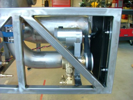
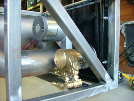
To complete the oil pump assembly I had to fabricate a new pump bracket. The bracket needed to position the pump motor in a way that would allow it to also be used as a cooling fan for the oil cooler. I came up with a design that fit into the front corner of the engine frame, saving as much space as possible. Hose clamps hold the pump motor and pump to the bracket. A model airplane propeller is used for the cooling fan.
|
|
|
|
 |
|
|
|
 |
|
|
|
A cross member was welded into the GR-7s engine frame to support the oil pump assembly. The final fit came out very nicely.
|
|
|
|
 |
|
|
|
 |
|
|
|
I now have the majority of the hydraulic system worked out. I only have to add the pressure sensor and plumb the system before I test it out. I will then be able to fill up the system with oil and test out the turbos bearings and seals. Once I verify that the turbo is in good shape I will be able to continue on and get the flame tube/evaproartor assembly built. Check back soon to see the continuation of the GR-7 engine!!!
Till then....
Don Giandomenico
|
|
|
|
 |
|
 |
|
 |
|