|
|
|
|
|
|
|
|
|
|
|
|
|
|
|
|
|
 |
|
 |
|
|
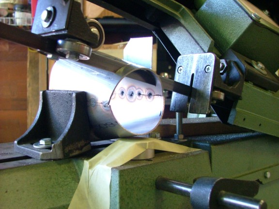
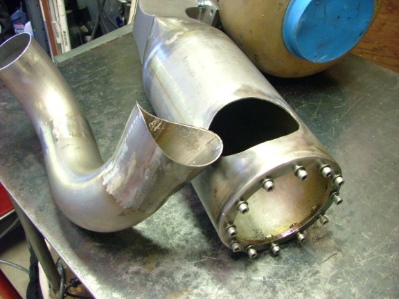
I constructed the diffuser out of the remainder of the u-bend pieces. I cut two identical halves that when joined formed the bell of the diffuser. Using the TIG welder, I tack welded the bell together and then trimmed the smaller end profile to match the 3 SS inlet tubing. The u-bend segments were then tack welded together so I could measure out the additional cuts that would be needed.
|
|
|
|
 |
|
 |
|
|
 |
|
 |
|
|
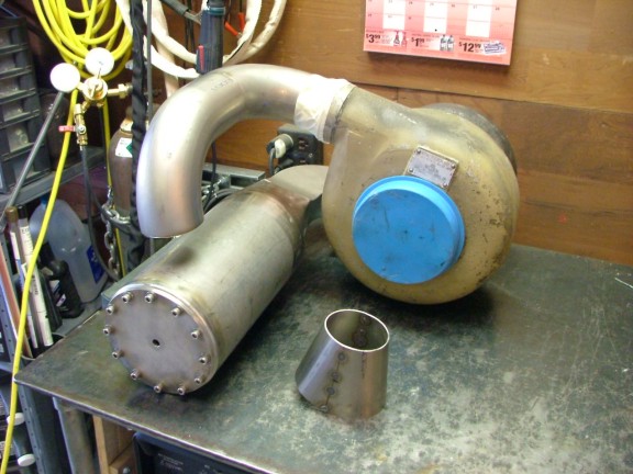
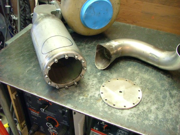
Using the plasma cutter I trimmed off the bell end to fit the round combustor side profile. Some fine tuning with the grinder helped make a perfect fit. Once the diffuser was tack welded and fit checked against the combustor I prepared it for final welding.
|
|
|
|
 |
|
|
|
The 3 u-bend has a wall thickness of 0.060 which is fairly thin for a large pipe diameter. This would be my first attempt at welding such a thin stainless with my TIG welder so I would have to be careful. The bend, as well as all of the stainless, was fairly pricey so a mistake would not be good. During the last few months, I had been getting e-mail tips on welding stainless from my readers. One tip I found helpful was the implementation of a process called back purging.
Back purging is a process where shielding gas is fed from both sides of the weld joint preventing atmospheric contamination/oxidization of the weld. If this process is not used there can be a sugaring effect where the back side of the weld will bubble up and form a crusty black sugar like substance. In essence, the glowing hot metal reacts to the atmosphere and in the unprotected environment produces sugaring. To back purge my welds I needed to build a gas delivery system to feed the argon into the inlet ducting.
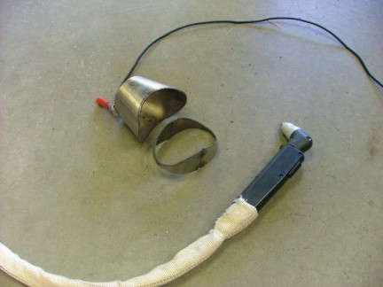
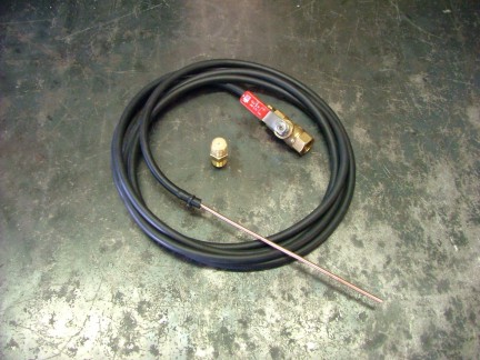
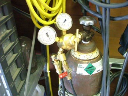
I built a simple orifice regulator and valve to connect to my argon tank regulator in which a rubber hose is attached. The rubber hose has a copper stinger at the end which is used to deliver the gas to the required area. I designed the orifice to meter the gas to a third of what the torch head is flowing. If the torch flows 20 CFH the back purger will flow 6.5 CFH (Cubic Feet per Hour). Because the gas is confined inside of the ductwork, less volume will be needed to shield out the atmosphere.
|
|
|
|
 |
|
 |
|
|
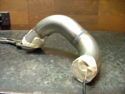
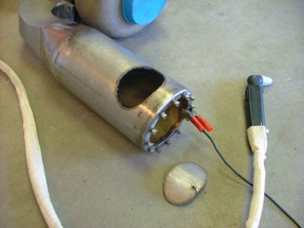
I was now ready to final weld the segments together. I inserted the back purging hose to one of the duct ends and covered them up with masking tape. (I later learned that aluminum foil works better than tape as it can handle the heat better) I set up the TIG welder to about 110 amps max and proceeded to weld the joints. During the process, the gas purging system was flushing out the ducting with a steady flow of argon. This was especially important to use on the thinner stainless as it has a greater tendency to sugar over thicker pieces.
|
|
|
|
 |
|
|
|
After the welds were complete, I ground them flat and used the flap disk to smooth out the joints.
|
|
|
|
 |
|
|
|
The inlet duct was put into position so I could mark out where I needed to cut for the combustor entry port. After marking out the needed hole I broke out the plasma cutter for a little freehand cutting.
|
|
|
|
 |
|
|
|
Once the port was cut out, a die grinder was used to clean up the slag on the inside edge of the hole. The pieces were then wire brushed and cleaned in preparation for welding.
|
|
|
|
 |
|
|
|
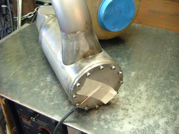
This weld was basically the whole ball of wax. If I botched this one, it would take a lot of cutting and grinding to fix. I proceeded by tack welding the duct to the inlet port and installing the back purging stinger to start flushing out the combustor.
|
|
|
|
 |
|
|
|
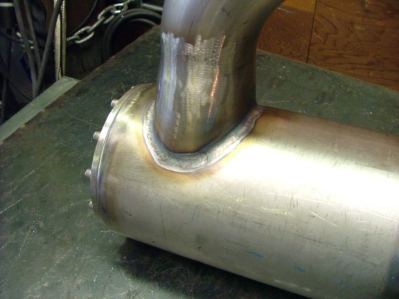
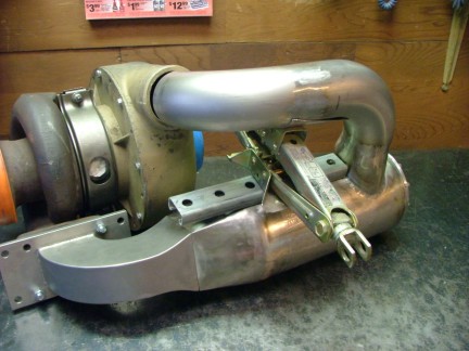
To prevent any movement or warping during the weld, I chose to spot weld all around the diffuser/combustor joint. I then very carefully laid down the final bead, adding just enough filler rod to form a clean fillet. I did not want to undercut the thin walled ducting so I paid close attention to the heat control setting as well. After a few minutes the weld was complete, no worries!!!
|
|
|
|
 |
|
|
|
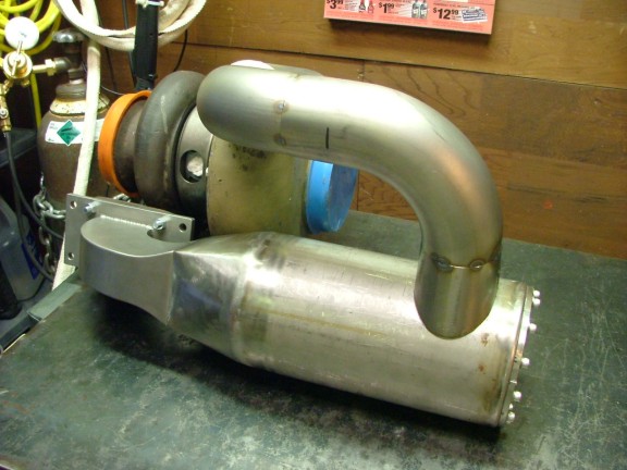
I installed the combustor onto the turbo to see if any warping occurred during the welding process. Sure enough, the inlet duct had warped about a 1/2 off of the compressor outlet. To fix the problem I used an old car jack that fit between the combustor and inlet duct. I cranked on the jack until the ducting met the compressor outlet and fixed the problem. I was surprised at how strong the 304 stainless was though. When I was done I had noticed that the process had bent the one ton jack out of shape :0)
|
|
|
|
 |
|
|
|
I now only needed to build the evaporator/flame tube assembly to complete the combustor. This will be the heart of the GR-7 and require the most research and development. Therefore I decided to wait on building the experimental evap/flame tube part of the project. There are so many other systems that need to be completed before testing that I decided to tackle the familiar systems first.
The next logical step was to build an engine frame to hold all of the components together. The combustor, turbo, hydraulic system, fuel system, ignition, starter, ECU and support systems would all have to fit into the engine frame. I needed to develop a frame large enough to fit all of these systems and yet be small enough to fit into my future jet bike configuration. This would not be an easy task considering the T-50 is such a large turbo.
It became apparent that the engine frame would have to double up as a structural member of the jet bike to save space. The bikes rear-end could bolt to the frame as well as the triple tree making the bike a modular unit. This would eliminate the need to re-situate all of the engines systems into the bikes frame when the time comes. I only had to add a few structural supports to the design to make this possible.
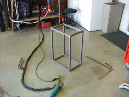
The final dimension of the frame would be 18 wide X 26 long and 12 high. This design will allow the engine to sit in the frame with the centerline of the turbine shaft on the centerline of the bike. This is important to me as the thrust vector should be in line with the wheelbase for stability reasons. Although the frame design is a lot wider than I originally planned on, it would be necessary for the proper function of the engine.
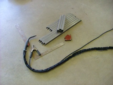
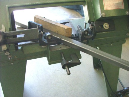
Having the basics down on paper, I started cutting up the 0.060-1 square tubing and welding it together.
|
|
|
|
 |
|
 |
|
|
|
 |
|
|
|
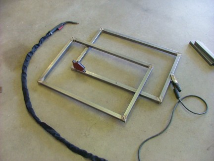
To fabricate the frame correctly, I used a large framing square to continually check the angles of the corners. An out-of-square frame will only complicate things later.
|
|
|
|
 |
|
|
|
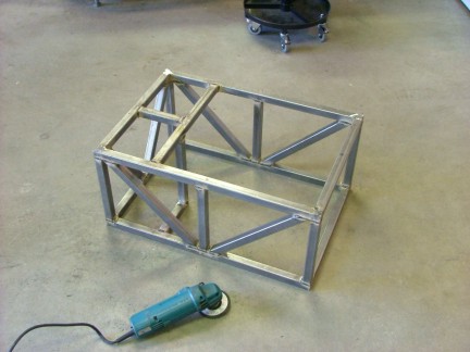
Bracing members were added to the sides and back of the frame to endure future structural loads.
|
|
|
|
 |
|
|
|
The exposed welds were ground flat and then flap disked to finish the process. Boy I tell you, an elephant could stand on this thing for sure :0)
|
|
|
|
 |
|
|
|
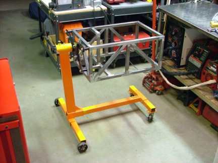
With the basic construction out of the way I was able to mount the frame to my automotive engine stand. Attaching the frame to the engine stand will allow me to work on the GR-7 at a comfortable work height. I can also turn the engine over to reach parts on the underside of the frame. Cool stuff!!!
|
|
|
|
 |
|
|
|
 |
|
|
|
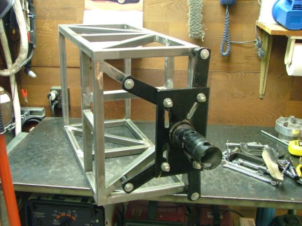
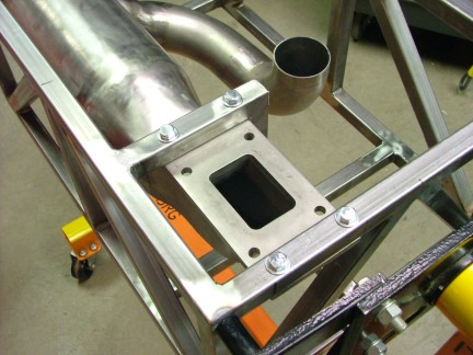
My new frame was ready for the combustor to be mounted. I measured out the holes needed for the combustor mounting hardware and drilled them through. Some 3/8 bolts were then used to hold the combustor/turbo flange plate to the frame.
|
|
|
|
 |
|
|
|
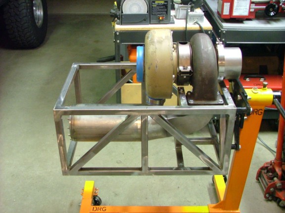
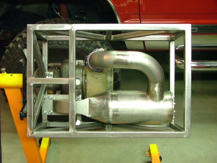
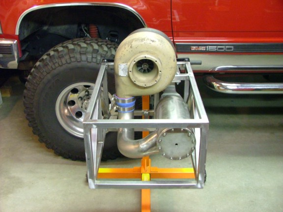
I installed a reinforced silicone reducer coupling to the compressor outlet and then dropped the turbo into place. 3/8 bolts were then used to secure the T-50 to the flange plate. I love it when a plan comes together!!!
|
|
|
|
 |
|
|
|
 |
|
|
|
 |
|
|
|
 |
|
|
|
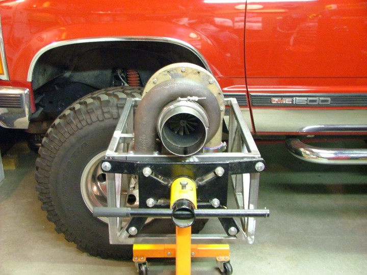
Having the frame ready will help me to visualize where I can install key engine components. Different combinations of component layout can now be physically tested which will greatly help me to choose the best configuration for the build. I guess I have my work cut out for me :0) There are so many things to build that I cannot think about all of the systems or I will get discouraged. One project at a time will have to be my motto from now on.
I hope to be able to get into the hydraulic/lubrication system next so check back for the next post soon!!!
Until then, take care................
Don Giandomenico
|
|
|
|
 |
|
 |
|
 |
|