|
|
|
|
|
|
|
|
|
|
|
|
|
|
|
 |
|
|
|
 |
|
|
 |
|
|
|
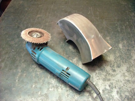
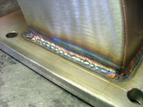
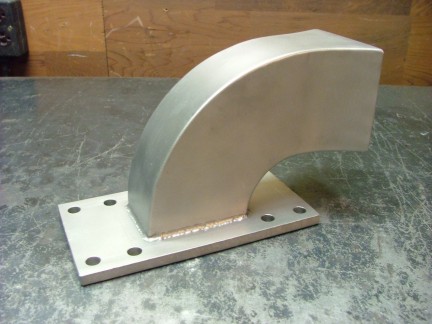
This weld was making me a little nervous as there was considerable time and money invested into this piece. One mistake could send me back to the drawing board so I practiced welding some scrap SS before I attempted the weld. After completing a couple of acceptable welds, I sat down and welded the final joints on the elbow. I was pleasantly surprised by what I was able to do with my novice TIG machine. The weld was slightly undercut but otherwise clean and presentable. Happy-happy, joy-joy!!!
|
|
|
|
 |
|
|
|
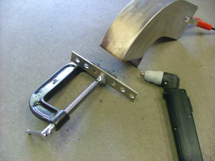
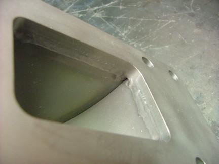
For added strength, I carefully welded the inside joint. The TIG process is great for laying down narrow beads as the heat can be focused very tightly.
|
|
|
|
 |
|
|
|
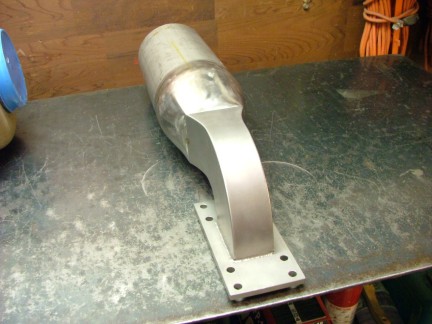
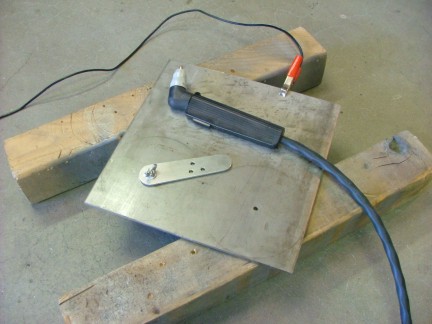
Needless to say, I was very happy with my progress. I proceeded to check the flange for warping and corrected a slight bow by bending it straight. I then used my belt sander to flatten out any high spots on the flanges mating surface. I now only had one more process to complete on the elbow before moving on to the combustor housing. I wanted to add a permanent finish to the stainless that would give the combustor assembly a uniform look. By using a bead blasting cabinet, I could apply a matte finish to the elbow and the rest of the combustor parts. I had purchased a bead blasting cabinet a few months prior so I was eager to try this process on the new part.
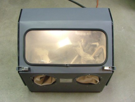
A bead blasting cabinet is used to clean or polish metal parts using a glass bead media. The glass bead is pneumatically thrown at the metal part with a blasting gun, leaving a clean matte finish. The cabinet has rubber gloves built into the front of it in which the operator can manipulate the parts and blasting gun without being harmed by the blasting process. I loaded up my new cabinet with a fine glass bead and started blasting the elbow part.
|
|
|
|
 |
|
|
|
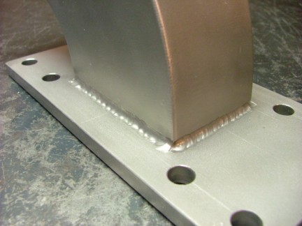
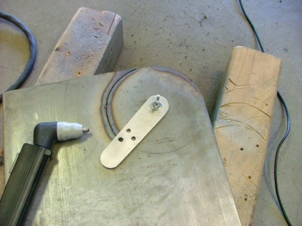
After 10 minutes of blasting, the elbow part was done. The matte finish covered up any imperfections in the metals surface giving it a very professional look. I love that silver-gold tone stainless steel has!!! :0)
|
|
|
|
 |
|
|
|
 |
|
|
|
 |
|
|
|
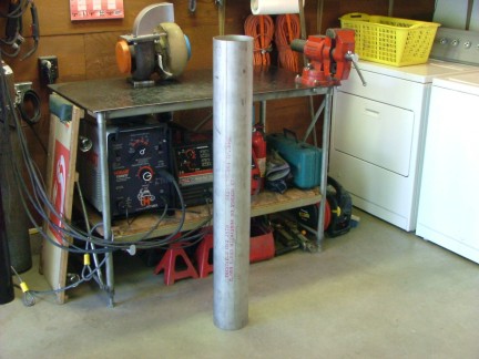
The next step was to build the combustion chamber that would connect to the elbow duct. To help in designing the combustion chamber I employed my GR-1 Combustor Formula. The formula helped me select the proper size stainless steel tubing needed for the build as well as outlining the proper dimensions of the combustor. I had purchased the nearest trade size of tubing to the formulas suggested dimensions which were calculated off of the turbos inducer size of 75 mm. The formula had suggested a 157.5 mm combustion chamber ID which I had acquired some 6 X .0985 (2.5mm) wall 304 SS tubing for. The 6 tubing has a ID of 147 mm which is only 7% smaller than the formulas suggested size.
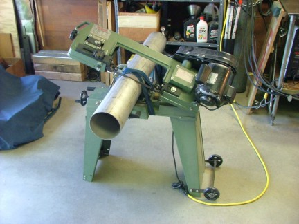
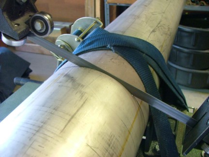
For the combustion liner or flame tube I needed a 97.5 mm ID tube (according to the formula). For that I was able to find a 4 X .0785 (2mm) wall 304 SS tube which has an ID of 97.3 mm. These two pieces of tubing would be the basis of the combustor and the heart of the GR-7 engine. To start the fabrication process I needed to cut the proper length of 6 SS tube from the 4 piece I had purchased earlier. To do this I employed my trusty horizontal band saw. I had to strap the tubing to the band saw as the vise would not grip the tubing :0/
|
|
|
|
 |
|
 |
|
|
 |
|
|
|
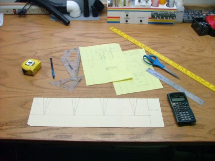
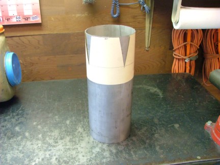
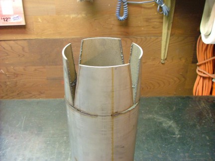
After I finished cutting the tubing I started designing the combustion chamber taper which would allow it to be connected to the elbow duct inlet. To taper the 6 tubing I needed to carefully cut wedges out of it. The wedge taper cuts will allow me to reduce and square out the 6 CC (Combustion Chamber) tubing. By using a paper template, I was able to lay out the cuts on the tubing with a marker.
|
|
|
|
 |
|
|
|
 |
|
|
|
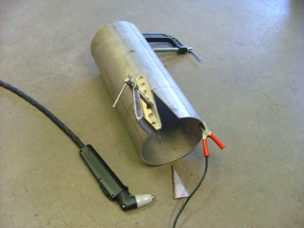
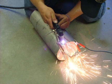
To cut the 304 tube I used my plasma cutter in conjunction with a straight edge. I clamped the straight edge to the pipe and drug the plasma cutter along side of it. This process saved a bunch of time over saw cutting the wedge cuts.
|
|
|
|
 |
|
 |
|
|
 |
|
|
|
 |
|
 |
|
|
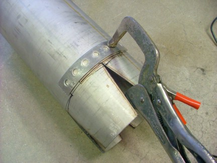
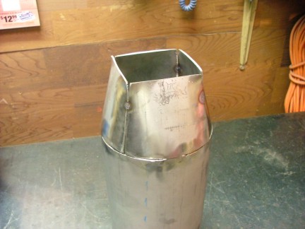
After the cuts were completed, I ground off the slag with my angle grinder. I then flattened the ends of the taper segments to match the elbow inlet profile. Finally the segments were pulled together and welded with the TIG machine.
|
|
|
|
 |
|
|
|
 |
|
 |
|
|
 |
|
|
|
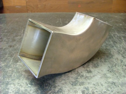
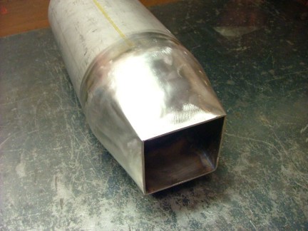
Having the previous experience of fabricating this kind of taper was priceless at this point. I was able to complete the taper fabrication in just under an hour and a half :0P I finished off the fabrication with the flap disk process and then tack welded the combustion chamber to the elbow inlet. I decided that I would not final weld the CC to the elbow so later I could perform combustor bench tests. Being able to remove the elbow for testing will allow me to see inside the flame tube and make the adjustments needed for proper fuel combustion.
|
|
|
|
 |
|
|
|
 |
|
|
|
 |
|
|
|
I now needed to build the combustor flange plate assembly which would cover up the back end of the combustor tube. I grabbed the 1/4 304 SS plate I had procured earlier and planned out my strategy. I had to cut two identical disks out of the 1/4 plate to fabricate the flange ring and end plate. I had tried to cut the SS plate with my bandsaw but ruined a brand new blade in the attempt. Seems that this piece of alloy was showing me how susceptible stainless is to work hardening. Only after a few seconds of cutting the stainless, the blade was destroyed as the work hardened stainless flattened the bands teeth. This was getting me nowhere fast!!!
I had to cut the steel somehow so I resorted to using the plasma cutter once again. The 12 amp plasma cutter I have is good for up to 1/8 steel so I would be stretching its abilities by 100%. I fabricated a circle cutting jig out of some aluminum plate that would guide the plasma cutters torch head during the cut.
|
|
|
|
 |
|
|
|
 |
|
|
|
Cutting the 1/4 plate was a slow going process. The plasma cutter was clearly out of its league here but made the cut nevertheless. This would be a much easier job with a 35 amp plasma cutter. Christmas is only a few months away you know :0)
|
|
|
|
 |
|
|
|
After cutting out the two disks (not shown) I prepared the bottom flange disk by grinding off the slag so it would fit into the 6 combustor tube.
|
|
|
|
 |
|
|
|
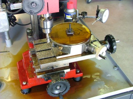
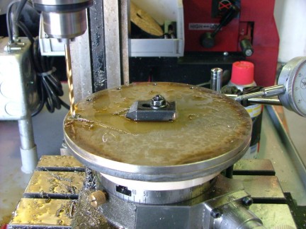
I was now ready to machine the combustor end plate out of the second 1/4 SS disk. The disk needed to be trimmed to a diameter that would not overhang the combustor flange ring. To do this I mounted the disk onto my rotary table and used my mill to trim off the outer edge of the disk with an end mill. I had found out through experimentation that an end mill works better than turning the disk on the lathe as I could not get a lathe bit to last more than a few minutes. I tried carbide and high speed steel lathe bits and all seemed to fail in short order.
The high speed steel end mills I was using earlier were lasting a long time as long as I used cutting oil and slow head speeds. Maybe a better lathe with more power could turn the disk at a much slower speed keeping the heat down. Once again, only a couple of months to Christmas!!!
|
|
|
|
 |
|
|
|
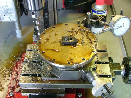
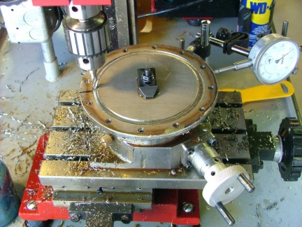
Once the end plate was trimmed to size I stacked it on top of the flange disk and mounted them both to the rotary table. I used the rotary table to index the twelve bolt holes that would be used to secure the end plate to the combustor flange ring. An 1/8 pilot bit was used to pre-drill the holes witch would make the final cut easier. A 1/4 bit was then used to size the final holes.
|
|
|
|
 |
|
|
|
 |
|
|
|
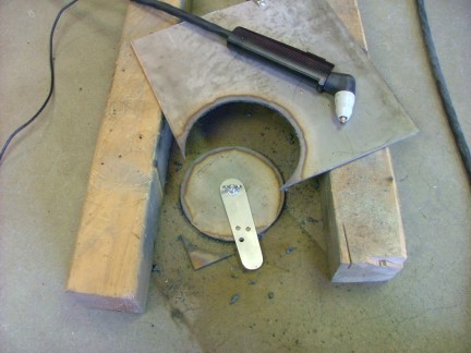
I now needed to cut out the center hole in the combustor flange to complete the assembly. I did not want to try cutting the hole out with my plasma cutter as the heat would probably warp the disk out of shape. I had such good luck using the end mill method before so I used it again. By using a small end mill I was able to plunge cut a hole in the flange plate without distorting its shape. The process took a little while but was worth the effort.
|
|
|
|
 |
|
|
|
 |
|
|
|
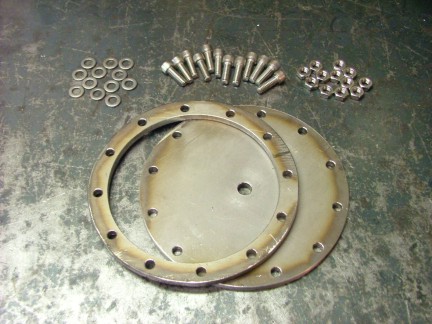
The finished parts looked good and I was eager to get them installed on the combustor tube.
|
|
|
|
 |
|
|
|
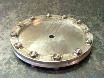
I decided to TIG weld stainless steel nuts to the inside of the flange plate to accommodate the 1/4-20 end plate bolts. This would eliminate the need to tap the difficult alloy and risk breaking a tap off into a bolt hole. I cannot get over the precise controllability of the TIG process. Very cool stuff!!!!!
|
|
|
|
 |
|
|
|
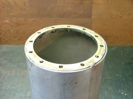
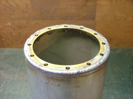
All I had to do now was to carefully weld the flange ring into the combustor tube. Heat could be a problem so I carefully pre-welded a few key points to prevent the ring from warping out of shape.
|
|
|
|
 |
|
|
|
I cleaned up the weld area with a wire brush and proceeded to lay down the final weld. I used a stainless filler rod to supplement the weld bead so it wold not undercut the flange plate.
|
|
|
|
 |
|
|
|
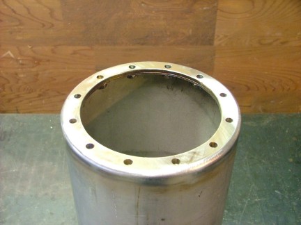
After the weld was completed I used the flap disk method to round out the weld bead. I then used my trusty belt sander to surface the flange ring flat.
|
|
|
|
 |
|
|
|
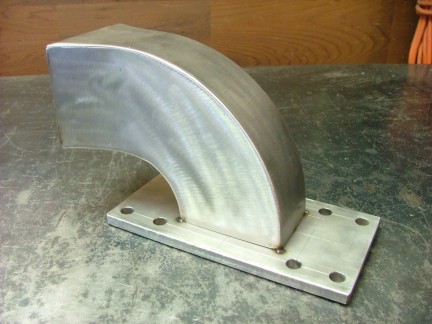
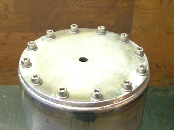
Once completed, the end plate assembly was ready for a fit check. I used 316 stainless steel hardware to bolt on the end plate. An anti-seize agent was used on the treads to prevent the stainless bolts from sticking in their holes. Stainless has a funny way of seizing to itself very easily. This would be a bummer considering the amount of work that was put into this piece.
|
|
|
|
 |
|
|
|
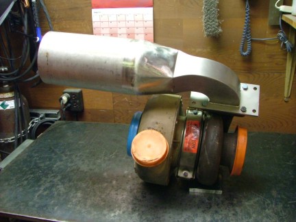
The next step will be to configure the combustor inlet ducting and weld it to the combustor tube. It wont be long before the GR-7s basic form takes shape. With the combustor mounted to the turbo, I will be able to get an idea of where to put the engine components to conserve space effectively.
To be continued.................
Don Giandomenico
|
|
|
|
 |
|
 |
|
 |
|