|
|
 |
|
|
Posted on July 3, 2005
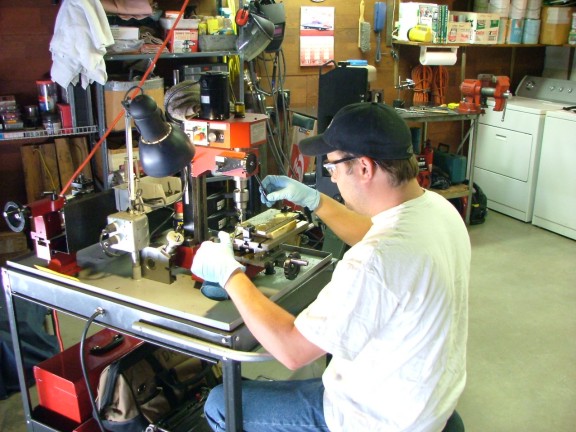
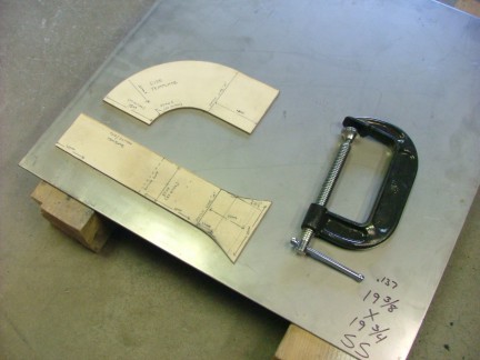
After researching different methods of working with the 304 stainless steel alloy, I set out to build my combustor. I had never tried to cut, machine or weld 304 stainless before so this was all new territory for me. I put my VT-50 turbo on the workbench and began to mentally visualize a few different engine layout possibilities. Without hesitation I rolled out my mini machine shop and started fabricating the turbo flange for the VT-50.
|
|
|
|
Earlier I had purchased some assorted stainless steel pieces specifically for the GR-7s combustor assembly. One of the pieces was a 1/2 X 4 X 12 bar which I intended for use as the turbo flange. The 1/2 bar was just wide enough to span the flange on the VT-50s turbine scroll. To start the fabrication I needed to cut a few inches off of the bar so I rolled out my horizontal band saw. This would be my first attempt at cutting such a thick piece of stainless so I was very curious on how well it would go.
|
|
|
|
Stainless steel can be tricky to machine as it has the tendency to work harden if it is cut improperly. Work hardening occurs when a tools cutting edge rides on the workpieces surface instead of cutting and removing material. Hardening can also occur when a workpiece is machined with too high of a tool speed which can create excessive heat. Heat and pressure will form a hard shell on the workpiece that will be much harder to cut than the original base metal.
|
|
|
To successfully machine stainless steel, one should maintain slow tool speeds, sharp cutting surfaces, and constant feed pressures. Cutting oil can also help the process by cooling the tools cutting surfaces and also cool the workpiece as well. High speed steel or cobalt steel cutting tools seem to work the best at machining stainless as they can have a very sharp cutting edge unlike carbide cutting tools. A sharp cutting edge is very important as to maintain consistent material removal with every pass of the tool.
To cut the 1/2 SS (Stainless Steel) bar for the turbo flange, I used a carbon steel 18 TPI band saw blade with raker style tooth staggering. I set my feed pressure to the maximum and changed the band speed to the slowest setting. The slow band speed will help reduce heat and give the blade a fighting chance to survive the cut without becoming dull from heat damage. After a few minutes of sawing, the 1/2 bar was cut.
|
|
|
|
 |
|
|
|
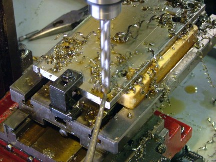
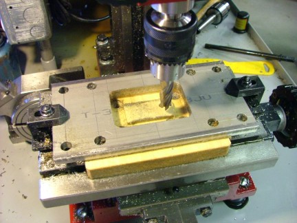
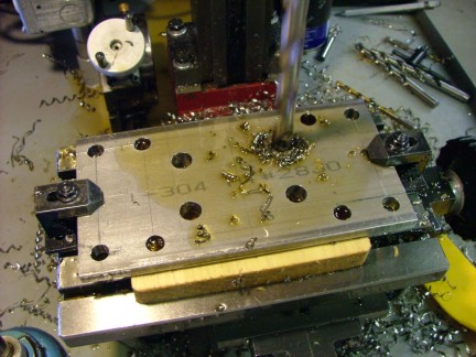
By carefully measuring the flange holes on the turbo, I was able to lay out the holes that needed to be cut in the 1/2 304 SS bar. I used a machinists scribe to mark where the hole centers would be located and then mounted the flange workpiece to my mill for machining. A dial indicator was then used to make sure that the workpiece was parallel to the cutting tables travel. I decided to use a small drill bit to make pilot holes at each hole location. The pilot holes will make the work of the larger drill bits easier as they will not have to remove as much material to penetrate the bar. The pilot holes also help to promote a good feed speed as you want the drill to constantly be removing material as to prevent the drill from riding the workpiece.
If the large drill bit has even a slightly dulled tip, it will not be able to keep up with the proper feed speed and may cause work hardening. To cool the drill bits I used a commercial cutting oil which I applied with a standard oiler can.
|
|
|
|
I was intrigued by the stainless shavings created by the drill bits. They would not break as easily as carbon steel shavings would and whipped around the bit like crazy. The drilling process had to be intermittently paused so I could lift the drill bit and pull the incredibly long shavings off the bit. I was amazed at the tensile strength of these shavings as I could hardly pull them apart, even with pliers!!! It would be easy to cut oneself very badly with one of these strings as they are sharp and strong.
Sometimes, during the drilling process, the drill would sing while cutting, causing an annoying metallic screech. Changing the tool speed would calm it down but for the most part I maintained a 400 RPM head speed.
|
|
|
|
 |
|
|
|
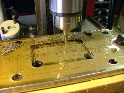
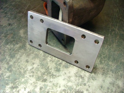
I had designed the flange to be an engine mount as well as a way to couple the combustor to the VT-50. The outer holes will be used later to help mount the turbo/combustor to the engine frame while the median holes will mount the flange to the turbo. The larger inner holes will be used as guides for the outside corners of the combustor exhaust port. I had spent some time debating on how I was going to cut between the holes to finish the exhaust port. One way would be to drill a series of holes and whittle my way through, finishing the hole with a file or grinder. Another method would be to cut the plug out with a large plasma cutter but unfortunately that would not be an in house option.
|
|
Finally I decided to use my mill to plunge cut some slots with a small 4-flute HSS (High Speed Steel) end mill. This process took about 40 minutes to complete and required a number of passes to chew through the flange plate.
|
|
|
|
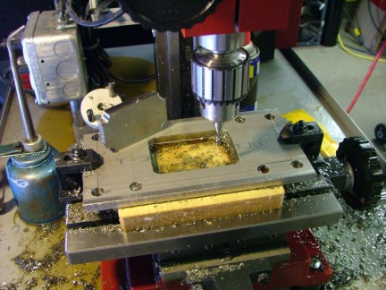
Once the plug was removed I was able to use a larger end mill to cut a finished surface inside the flange port.
|
|
|
|
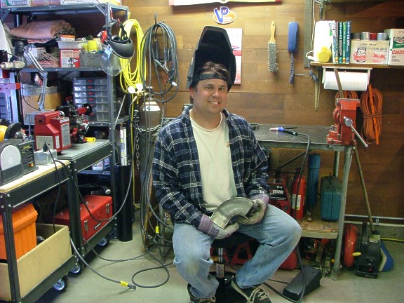
After a couple of hours of work I was finished and the product looked good.
One step complete and many to follow.......
|
|
|
|
 |
|
|
|
On my GR-5A engine, the combustor is perpendicular to the turbos axial plane which leaves it sticking out like a sore thumb. I cannot use this configuration on the GR-7 as the engines combustor would be sticking out of the side of my proposed jet bike. To fix the problem I needed to devise a way to build an elbow fitting that would allow the combustor to be mounted horizontally under the turbo. I had entertained the idea of buying a SS 90 deg. fitting to weld between the turbo flange and the combustor. The only problem with using a factory elbow fitting is that the rectangular profile of the turbo flange would not match the round profile of the elbow.
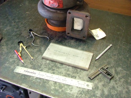
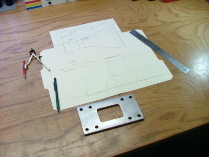
There would be fabrication difficulties in getting the round profile of the small radius elbow to flow into the square turbo flange inlet. To solve this problem I decided to make my own elbow out of 304 SS plate. This design was ideal as I could make the elbows radius to any size I wanted. I would just have to figure out how to connect the round combustor to the square elbow fitting. After measuring the compressor housing/combustor clearance, I was able to decide on a 3.5 (center line) radius bend. This would give the combustor about an inch clearance from the compressor housing. I started out by drafting a scale drawing of what I wanted.
|
|
|
|
 |
|
|
|
Because of the inherent rectangular profile of the flange/elbow, I decided to add a bell profile to square out the elbow inlet. This addition will make a true square profile on the inlet and allow for an easier job of tapering the round combustor housing to join with the elbow. It all looks good on paper but will it work in the shop..........
|
|
|
|
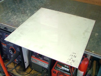
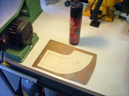
As part of my SS stockpile I had acquired some 0.137 thick 304 SS plate. It seemed to be just the right thickness to support the combustor and yet be light enough to keep weight down. All I had to do was figure out a way to cut the plate to my drawings specifications. I had thought of an idea earlier that I had not tried before and this was the perfect opportunity to test it out. If I could make 1/8 thick templates out of my drawings, I could use my plasma cutter to outline and cut around the templates.
|
|
|
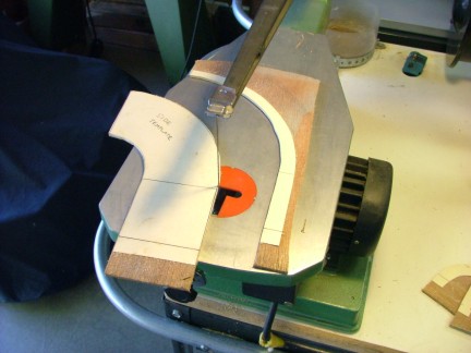
I tried out a small cut using some 1/8 plywood that was C clamped to the SS sheet. By dragging the plasma cutter around the plywood template, I cut out the test piece. I used a grinder to clean up the cut edges and then measured the offset needed to compensate for the plasma cutter head width and grinding allowance. With this information I was able to adjust my drawings for a 3/32 offset all the way around. Once the drawings were modified, I glued them to a sheet of 1/8 plywood and prepared them for the scroll saw. Once cut out, the templates edges were sanded smooth.
|
|
|
|
I placed the elbow template on the SS sheet and clamped it down. By carefully dragging the plasma cutter around the edge of the template I cut out the first piece.
|
|
|
|
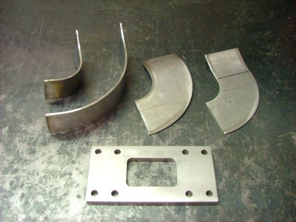
The plasma method seemed to be working well so I proceeded to cut out the rest of the elbow pieces. Once they were cut, I ground the outer edges to clean off the slag from the cuts. This method saved an incredible amount of saw cutting and I definitely look forward to using again later in the project.
|
|
|
|
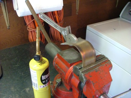
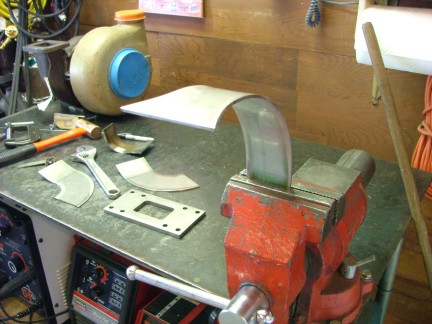
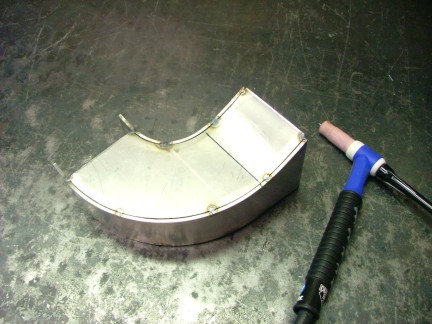
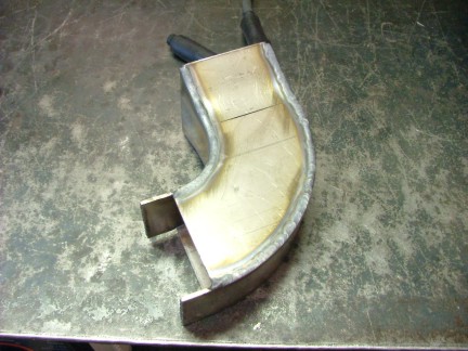
At this point, all of the parts were cut, ground and readied for forming. To bend/form the pieces I used some basic hand tools and my vise. The inside radius bend was assisted by use of a MAPP gas torch to soften up the temper.
|
|
|
|
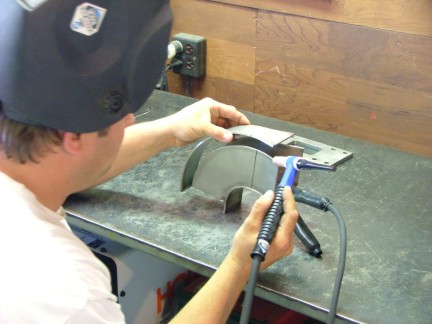
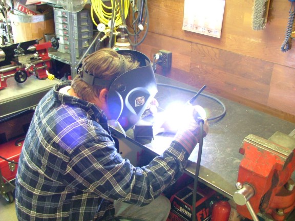
All of the elbow parts were complete which left the task of welding them together. My small MIG (Metal Inert Gas) welder would easily weld the SS using a mild steel electrode wire. Unfortunately the mild steel weld would not have the same composition of the SS and would eventually oxidize. This would be unfortunate especially after going through all of the trouble fabricating the 304 alloy. The only proper way to weld the SS would be to weld it together using the same alloy. This could be done by loading a stainless steel electrode wire into my MIG welder and using a special helium/argon/co2 mix shielding gas. Although this setup would work, I would not have the precise heat control necessary to weld the thinner SS metals I hope to use in future fabrications.
TIG (Tungsten Inert Gas) welding has been one of the industry standard methods of welding stainless steel and other exotic alloys. TIG welders use a non-consumable tungsten electrode torch to create an arc between the torch electrode and the metal being welded. This arc is capable of welding many different types of metals including stainless steel, aluminum, copper, titanium, nickel alloys and even cast iron. A shielding gas is fed through the torch to shield the electrode and molten weld pool. The shielding gas or gasses (typically argon, argon+hydrogen and argon+helium mixes) keep oxygen and impurities from contaminating the weld and in some systems also serve to cool the electrode and torch head.
A separately added metal filler rod is used to add metal to the weld if needed. A foot pedal is typically used to control the heat output of the torch which allows the TIG welder to make very precise welds. Unfortunately the equipment needed to TIG weld can be many times the cost of standard arc welding equipment making it difficult for the average garage builder to afford. Fortunately, with the advent of newer technology, manufactures have been able to produce economical TIG welders for the hobbyist. Wanting very much to be able to learn to TIG weld, I started looking to buy a machine that would benefit my research without killing my budget.
|
|
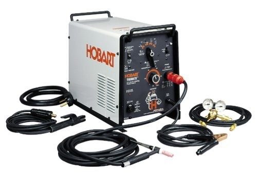
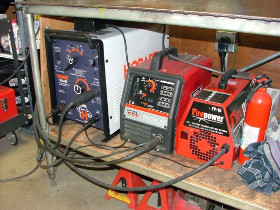
After a bit of research I decided to purchase the Hobart Tigmate. The Tigmate (also sold as the Miller Econotig) is an AC/DC TIG welder that is sold as a complete package (less the required shielding gas cylinder). The system includes a TIG torch and stick welding electrode cable as well as a gas regulator. The welder is capable of producing a 150 amp output which can be precisely controlled by an optional foot pedal or fingertip control unit.
|
|
|
|
The Tigmate has a street price of about $1300 USD which includes a foot pedal or fingertip controller. This price is hundreds less than similar units which made my decision to buy the Tigmate easy. Within 20 minutes of plugging in my Tigmate, I was practicing to weld aluminum! It wasnt to long before I was able to make presentable aluminum and stainless welds which I had originally assumed would be terribly difficult to learn. Although the difficulty level of TIG welding is much higher than MIG welding, the Tigmate simplifies the process greatly. Once again, having the right equipment is priceless!!!
|
|