 |
 |
 |
|
 |
|
 |
|
 |
 |
|
 |
|
|
|
 |
|
 |
|
 |
|
|
|
Posted on August 30, 2012:
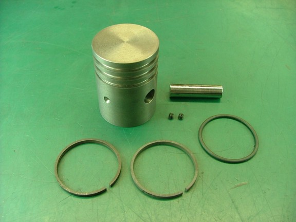
Hello again folks!!! I now have all of the parts to assemble the piston with the connecting rod. I gathered up the steel compression rings, oil O-ring, wrist pin and 4-40 set screws as seen below...
|
|
|
 |
|
|
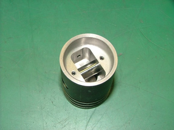
I checked the fit of the wrist pin and installed the two set screws to see how everything fit.
|
|
|
 |
|
|
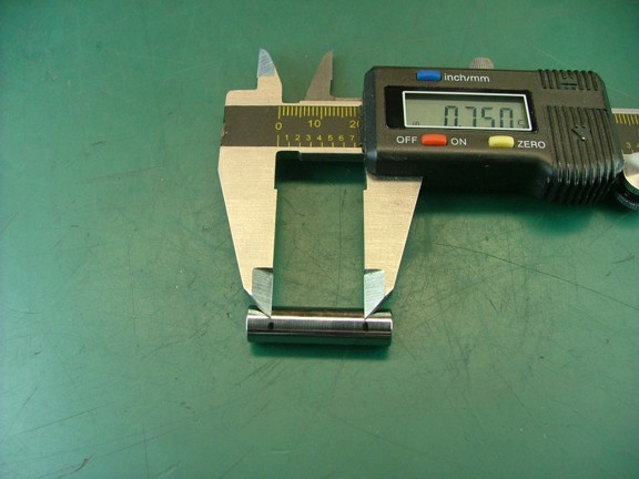
The next step is to grind a set of flats on the wrist pin so the set screws have a surface to clamp down on. This is important as the hardened pin will not allow the set screws to bite into the metal which could result in the pin shifting later on. I laid out two marks on the pin for grinding as seen below...
|
|
|
 |
|
|
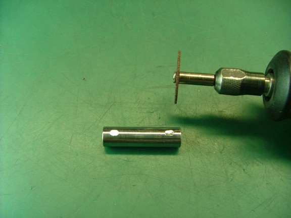
I used my Dremel tool to grind two flat spots on the pin as seen below...
|
|
|
 |
|
|
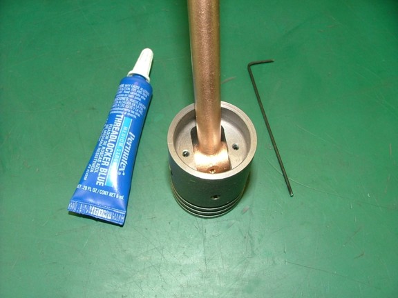
I cleaned off the pin and installed it into the piston and connecting rod. I then locked the set screws into place using some blue Locktite. Of course I made sure that the wrist pin’s flats were facing up before doing so.
|
|
|
 |
|
|
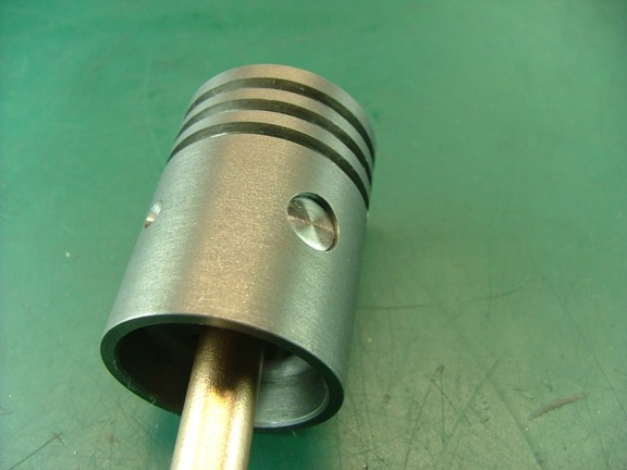
I checked to make sure that the wrist pin was centered in the piston before moving on.
|
|
|
 |
|
|
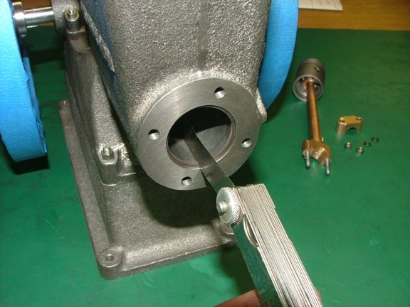
The next step is to make sure the piston rings supplied with the kit have enough end clearance. This is an important clearance as it allows the ring to thermally expand without hitting it’s own ends which could cause the engine to seize. I inserted each ring into the cylinder and made sure there was at least .004” clearance as suggested by the prints.
|
|
|
 |
|
|
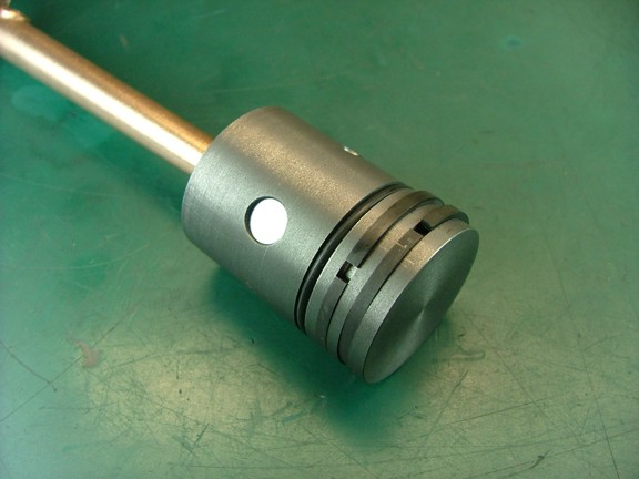
I now could install the rings into the grooves. I carefully widened (by hand) the top ring and pulled it over into the top groove. I then set the second ring by passing it over the first ring into the second groove. This is not a common practice however it allows the second ring to “ride” over the first ring which will prevent it from falling into the first groove. Lastly I installed the oil wiper O-ring into it’s groove as seen below.
Note: It is of the most importance that you expand the ring so that it stays round as to not induce an oval shape into the ring. This will cause the ring to not evenly press on the bore of the cylinder and thus cause a loss in compression.
|
|
|
 |
|
|
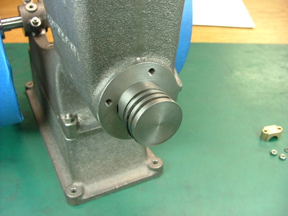
I lubed up the piston and rings with some 5-20 motor oil before installing it into the cylinder. I then compressed the rings (one at a time) with my fingers so that the piston could be inserted into the bore. Note: When the piston is installed on final assembly I will place the rings at 180° apart to improve compression. More than likely the rings will rotate on there own so this may or may not help compression in the long run...
|
|
|
 |
|
|
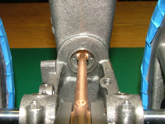
I connected the big-end bearing on the crankshaft and secured the cap into place. I then added a few drops of motor oil to each bearing for good measure.
|
|
|
 |
|
|
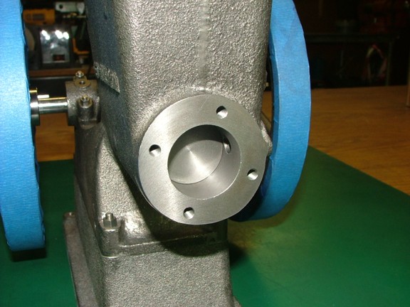
I cranked over the motor a few times to see if there were any tight spots. Luckily the piston and rod worked effortlessly in their new home. I could hear the new rings as they mated with the freshly honed cylinder. Looks good so far!!!
|
|
|
 |
|
|
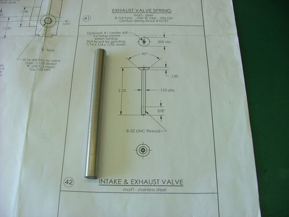
I can now move onto the smaller parts of the engine starting with the poppet valves. The valves are made out of 1/2” 303 stainless steel rod which is included in the optional Red Wing materials kit.
|
|
|
 |
|
|
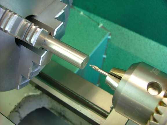
I started off by drilling a #1 center drill hole in both ends of the stainless rod.
|
|
|
 |
|
|
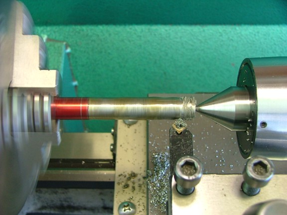
I scribed out two lines on the rod for the bottom and top of the valve leaving a little extra length to remove the center drilled hole later on (2.295” and 2.425” from end). I then started to cut down the rod to the desired diameter with ample cutting oil.
|
|
|
 |
|
|
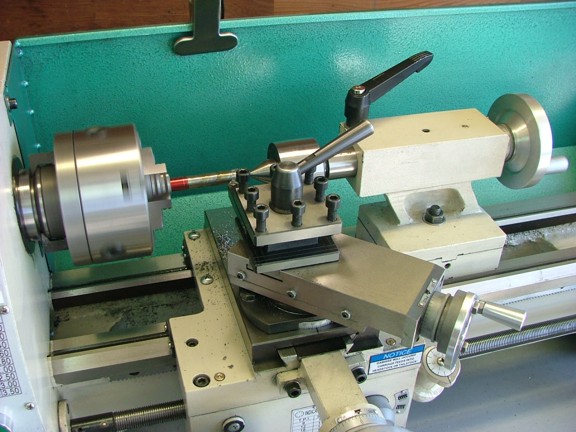
I turned the valve stem at 300 to 500 RPM, speeding up as the diameter got smaller. I also used a feed rate of .0035” IPR while making cuts at .005” deep per pass.
|
|
|
 |
|
|
Stainless is generally tough to cut so ample lubrication, proper cutting speed and depth are all important.
|
|
|
 |
|
|
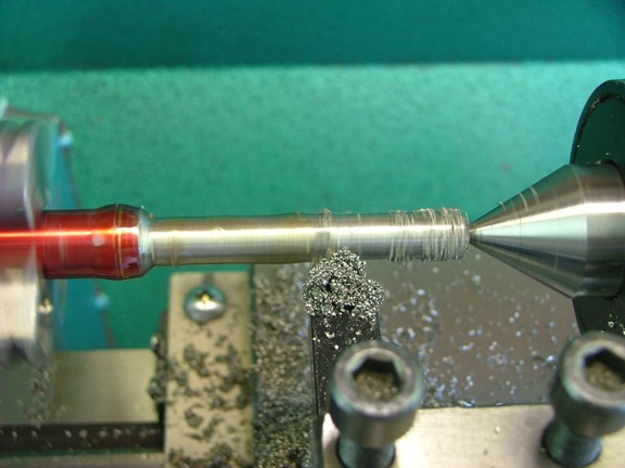
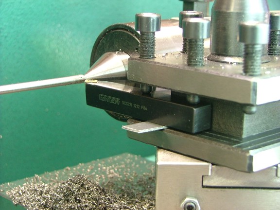
You can see below how I used shims to “balance” the indexable tool bit for proper height. This is a trick I found while trying to figure out how to adjust the tool bit’s height without a rocker tool post. I can adjust the two clamping screws until the tool bit’s edge is center of the workpiece as seen below.
|
|
|
 |
|
|
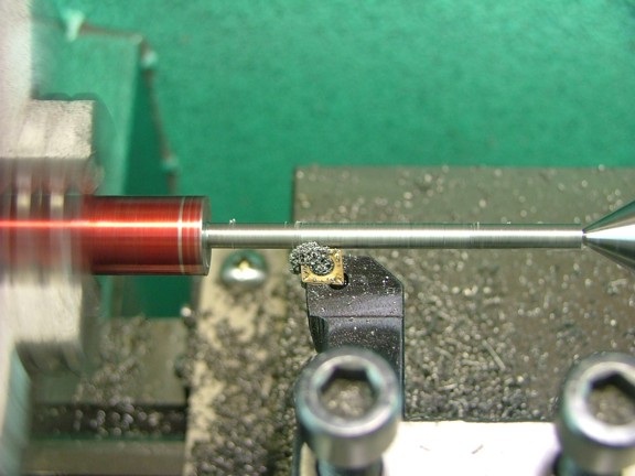
I continued to turn down the stem to a diameter of .158”.
|
|
|
 |
|
|
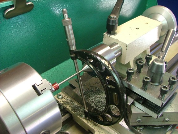
I carefully measured the stem with my calipers to make sure I was on track. I did this in several spots on the stem...
|
|
|
 |
|
|
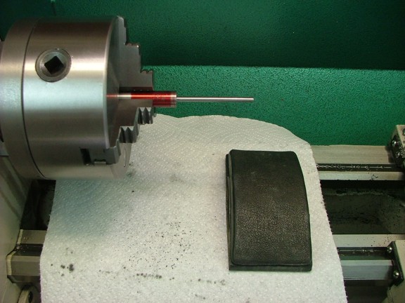
To get the last .002” I decided to sand the stem with some 320 grit sandpaper. I frequently checked my progress with the micrometer (not shown) until I was at exactly at .155” in diameter.
|
|
|
 |
|
|
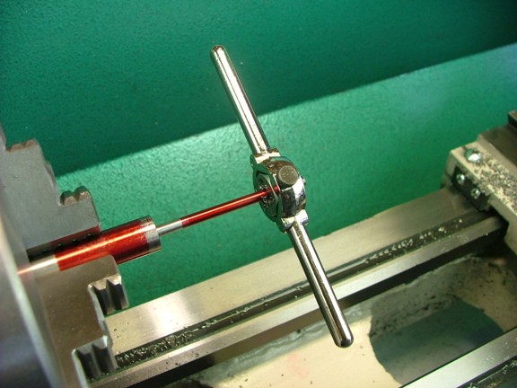
I applied some layout fluid to the stem and marked a line at 1.725” back from the bottom of the valve head (not shown). I then used an 8-32 die to thread the stem up to this line as seen below. I was very careful not to hold the die at an angle when starting it on the stem. It would be a real bummer to ruin the valve at this point. Note: There are tools that are designed to hold threading dies in the tail stock of the lathe which eliminate this risk of off center threading. I just happen to not own one yet :0>
|
|
|
 |
|
|
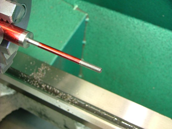
The threads at this point are a little longer than needed so that the stem can be ground flat later on...
|
|
|
 |
|
|
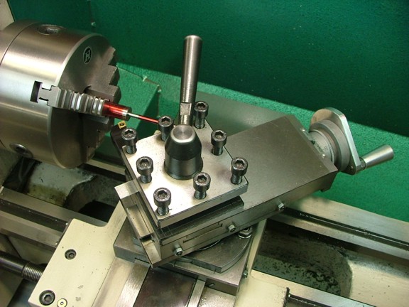
The next step is to adjust the compound rest to a 45° angle so that the face of the valve can be cut.
|
|
|
 |
|
|
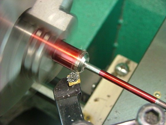
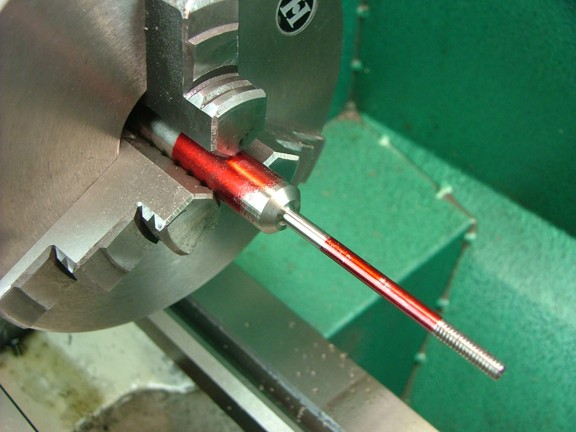
I used a indexable tool bit to cut the valve’s face or “seat” as seen below...
|
|
|
 |
|
|
I finished the cut so that the inside edge of the bevel was at a diameter of about .300”.
|
|
|
 |
|
|
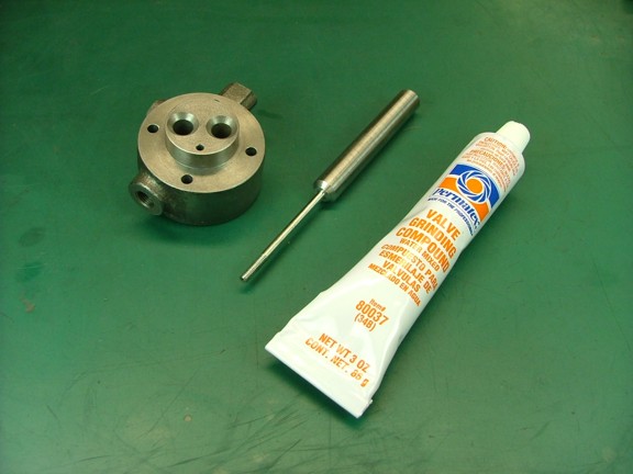
The next step is to grind or lap the valve into it’s seat. The purpose of valve lapping is to make a perfect mating surface for the valve to contact with so that the valve is air tight. This is typically done with an abrasive compound that can be applied to the mating surfaces (excluding the stem of course) and worked together to remove the “high spots” on the seats. For this I will be using some Permatex valve grinding compound (Cat# 80037). This is a medium grit compound used for lapping valves and is available at most auto parts stores.
|
|
|
 |
|
|
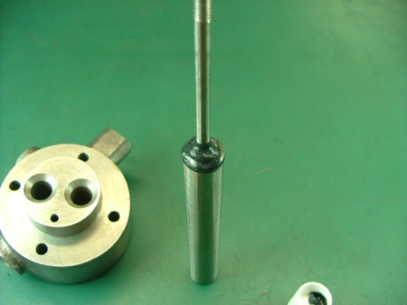
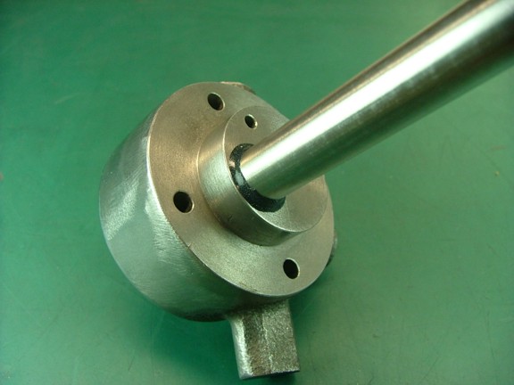
You may have noticed that I have left the head of the valve connected to the unmachined rod. This is so I have something to use as a handle to lap the valve into the head. I applied some compound to the valve’s face and inserted it into the intake side of the head. I was very careful not to contaminate the stem with any compound as this will ruin the tight tolerance needed for proper sealing.
|
|
|
 |
|
|
Years ago in Jr. high I remember taking a small engines course where we learned to lap valves. The one thing I remember is that in order to do a good job you need to do this by hand. We had used little wooden dowels with suction cups on the ends which attached to the valve head. We then rolled the dowels between our hands in both directions with medium pressure to cut the seats.
I remember specifically that you needed to turn the valve both directions or else the seat would be cut uneven. I used the same method for lapping these valves except I just used my fingers to rotate the valve back and forth with a light pressure. Too much pressure and the abrasive compound will be pushed out of the valve.
|
|
|
 |
|
|
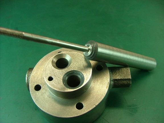
I lapped the valve for several minutes and then checked the progress by wiping off the compound. I was looking for an evenly dull grey finish on the valve’s face but I had not gotten there yet. I applied more compound and started lapping a little more...
|
|
|
 |
|
|
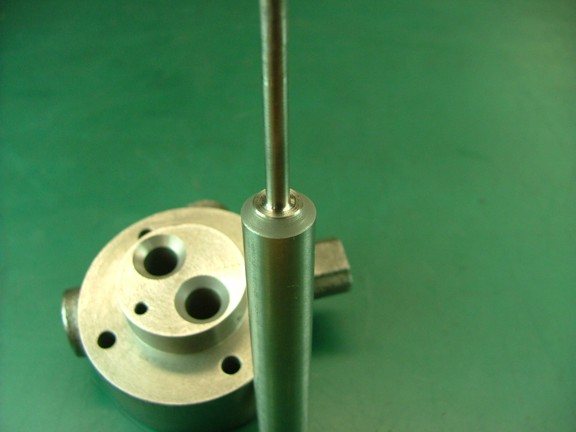
After a minute or two I removed the valve and inspected the progress. The face of the valve was evenly ground (seen below) so I could move on to finishing the head.
|
|
|
 |
|
|
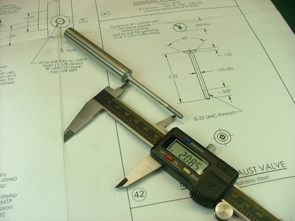
I measured out the final length of the stem to be about 2.085” from the bottom of the valve head (prints call for 2.120”). I then used my belt sander to grind off the excess (not shown). This also removes the centering hole I had made earlier for turning the stem. Note: You can always make the valve a little longer as the prints suggest and then trim them to fit your valve gear later on.
|
|
|
 |
|
|
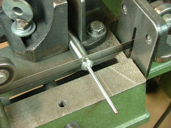
I moved the valve over to the band saw and removed the rod from the head as seen below.
|
|
|
 |
|
|
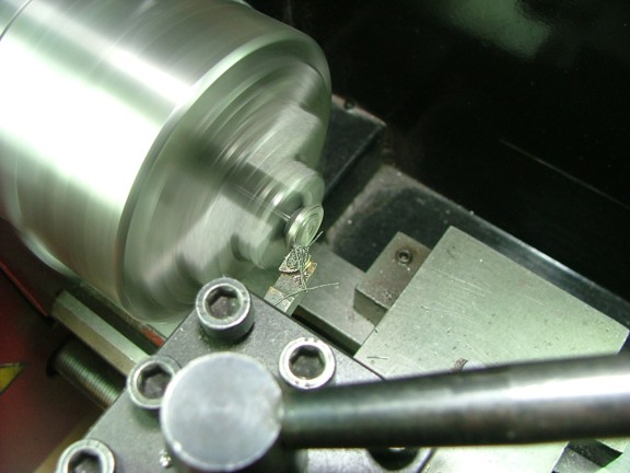
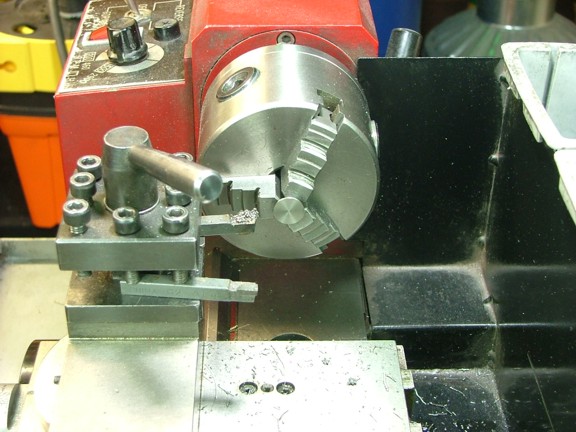
I now moved the valve over to my 7 x 10 mini lathe to trim up the head to a margin thickness of .030”.
|
|
|
 |
|
|
 |
|
|
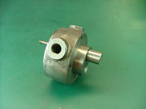
At last I had one of the valves finished :0P
|
|
|
 |
|
|
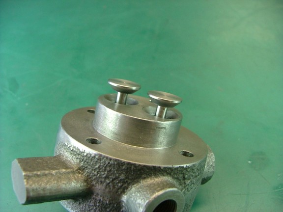
I proceeded to use the remaining valve stock to make the second valve utilizing the centering hole I had drilled earlier on the live center (not shown). This time the remaining stock on the head was much shorter so I had a smaller handle to lap the valve as seen below. It still worked well and I finished the valve head in the same manner as before.
|
|
|
 |
|
|
Note: I marked the tip of one of the valve stems with a groove so that I will know what valve belongs to what hole as they are not interchangeable (not shown).
|
|
|
 |
|
|
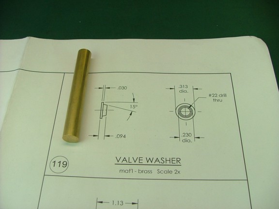
The next step is to make a set of valve washers. These washers center the valve springs on the valve stems.
|
|
|
 |
|
|
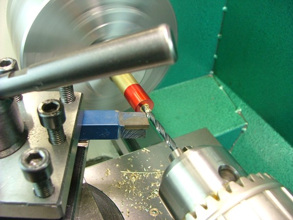
I started out by drilling a #22 hole .300” deep in one end of a 1/2” brass rod supplied with the materials kit.
|
|
|
 |
|
|
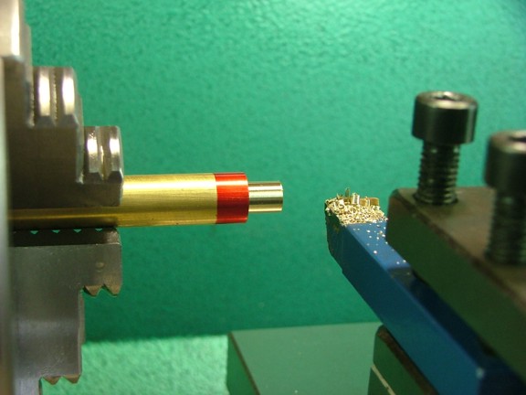
I now cut down a 3/8” wide section of the rod to a diameter of .313”
|
|
|
 |
|
|
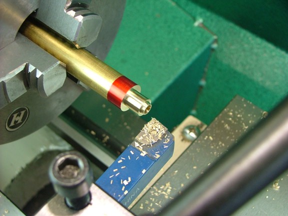
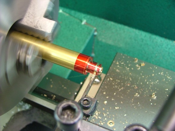
I set up the compound rest at 15° (not shown) and cut the tapered profile on the end of the washer as shown below. I did this by cutting down to .230” at .064” from the end and then I drew back the tool bit at a 15° negative angle which left the desired taper.
|
|
|
 |
|
|
To finish off the washer I used an .058” wide high speed steel parting tool to cut the washer free from the rod. This was done so that the washer’s final thickness was at .094”
|
|
|
 |
|
|
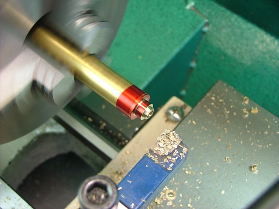
The second washer was cut in the very same manner...
|
|
|
 |
|
|
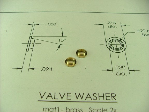
The finished product...
Addendum 12/28/13:
After running this engine for a while now I have discovered that using a valve washer on either side of each valve spring works better at keeping the spring centered (in lieu of only one per spring). I would suggest making four washers if you are set up for this part of the build and save some time should you decide to go with two per spring...
|
|
|
 |
|
|
I am really picking up speed here as I get closer to a finished project. Please join me again for the next episode of the Red Wing project.
Till then stay creative my friends!!!
Don R. Giandomenico
|
|
|
 |
|
 |
|
 |
|