The next project I wanted to work on was the exhaust nozzle or jet pipe portion of the build. The GR-7 still needed a suitable jet pipe to make the thrust it will need to push a ground based vehicle around. I wanted to design a pipe that would work efficiently with the VT-50 turbine and not cause too much stress on the engine. Ultimately this may require building and testing several different jet pipe designs to see which one will work best but for now I needed one to start with.
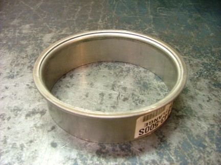
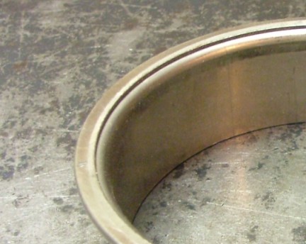
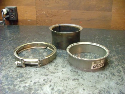
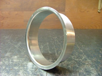
The basic idea behind jet propulsion is to take a mass of air (weight of air) and force it in a direction causing and opposite and equal force in the form of thrust. The amount of thrust depends on the air mass flow rate and how fast the air masss velocity is accelerated within the engine. A turbojet engine takes a relatively small air mass and gives it a large acceleration to create thrust. This is inversely proportional to a propeller based propulsion system which takes a large air mass and gives it a small acceleration to produce thrust. Fortunately for the turbojet engine increases in thrust can be achieved by using a exhaust nozzle to further accelerate the exhaust gasses. This is done by converging the turbine exhaust gasses into a focused jet hence the term jet propulsion. The tighter the nozzle, the faster the gasses have to travel through it to maintain the same mass flow. This of course requires more exhaust pressure from the turbojet engine, increasing its workload. To design a jet pipe for the GR-7 I would need to know what diameter to make the jet pipe nozzle. On my GR-1 engine, the nozzle was sized to 70% of the turbine exducers diameter (at the wheel). This worked out great for the GR-1 but may not work for the GR-7. Different turbos have different flow rates at different pressures so it may not be as easy as a 30% reduction in the turbine exit profile. If the nozzle is too narrow it will not allow the engine to breath and cause surging, overheating and starting problems. The turbine volute (scroll) inlet area seems to be an acceptable starting point for sizing a turbocharger jet pipe nozzle. On my VT-50, the turbine volute inlet (the 4-bolt inlet flange on the turbo) has about a 6.25 square inch area profile. This is equal to a round duct diameter of 2.82. This value, in theory is a safe diameter to start with for the GR-7 jet pipe. I wanted to build the new jet pipe out of 304 stainless steel. This would help the jet pipe resist corrosion and look pretty cool as well :0) Earlier I had purchased a v-band clamp and flange fitting to mate with the VT-50s turbine exducer. The mild steel flange fitting that came with the stainless clamp would be a less than desirable choice to weld to a new stainless jet pipe so off to the internet to find a stainless steel flange fitting After some searching, I located a local business called Burns Stainless that specializes in stainless steel and Inconel performance exhaust parts. Looking through their catalog I found a 5 v-band flange that is made of 304 stainless so I purchased the fitting to see if it would work on my VT-50. Once the part arrived I discovered it was not exactly what I was looking for. Seems that the new v-band flange was designed to fit a proprietarily designed flange system and would not fit the VT-50 turbo as is. The close-up below shows a doubled straight flange that will not fit to the angled v-band flair that is on the Cummins VT-50 turbo. Notice the angle of the mild steel flange (lower photo) compared to the stainless flange.
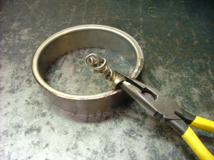
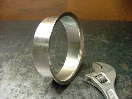
I decided to remove one of the doubled layers on the flange and shape the edge to fit the turbo. This way I could build an all stainless jet pipe. I used my angle grinder to remove the upper-outer edge of the doubled lip. Once the metal was removed I used my needle nose pliers to peel up the ring like a can of sardines. I then used the belt sander to clean up the outer edge.
A Crescent wrench was used to carefully form the taper needed to match the VT-50 turbos exducer and allow the stainless v-band clamp to work with it.
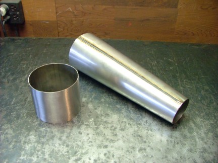
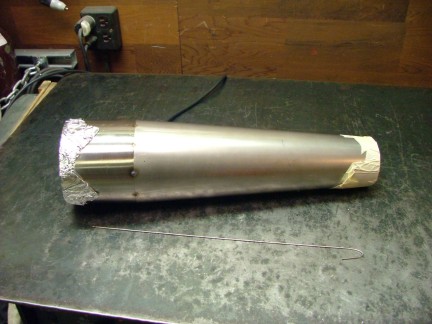
Now that the flange was out of the way I could focus on the jet pipe nozzle. Looking through the Burns catalog again I found an exhaust megaphone used on racing exhaust systems to increase piston engine performance. The megaphone is commonly used as a divergent duct (expanding in profile) at the end of the exhaust system which helps to reduce back pressure. I wanted to use the megaphone as a convergent duct (decreasing in profile) to act as a jet nozzle so I bought one to try it. The megaphone arrived the next day and it was a real beauty. It is made from a rolled and welded 20 gauge 304 stainless steel sheet and is 5 OD on one end and 2.85 ID on the other end. This was almost the exact size I needed for the jet pipe so I was pretty happy. I cut a short piece of 5 exhaust tubing to slightly lengthen the 14.5 long megaphone to about 19 long. The longer pipe will help to stabilize the exhaust gasses once they leave the turbine wheel and hopefully improve thrust a bit.
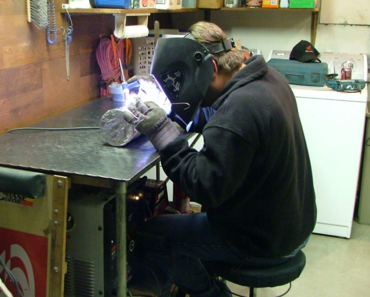
I fired up the TIG welder and proceeded to weld on the pipe extension. I used the back purge system to increase the strength of the weld. Notice the aluminum foil on the end of the pipe. This is used to help contain the Argon gas within the pipe during the welding process.
Once the weld was complete I used the flap disk on the angle grinder to remove the weld beads and smooth out the transition.
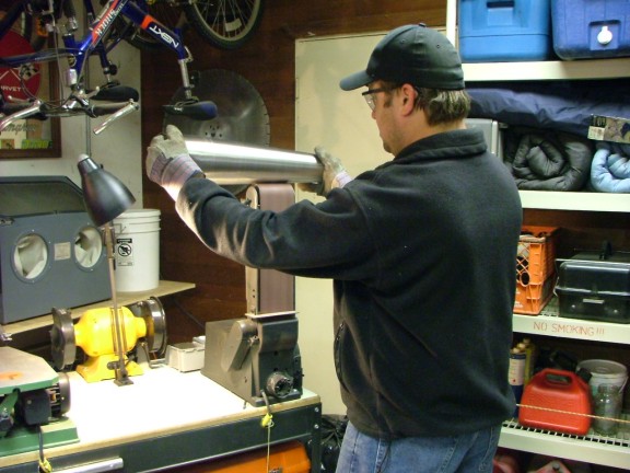
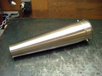
The next step was to give the jet pipe a brushed look by turning it on the belt sander. This home-brew technique of grinding the outside of round objects was something I stumbled on by trying it. To apply the brushed look to the stainless I let the round work piece ride on the 120 grit belt while I hold it with gloves. I allow the work piece to start to rotate but limit its speed by slightly gripping it with the gloves. I can then move the work piece left and right until the entire outside of the pipe has the brushed look. This process definitely takes some practice to perfect but really adds a professional look to round parts.
I use my belt sander in so many different ways that it ceases to amaze me on what you can do with one :0)
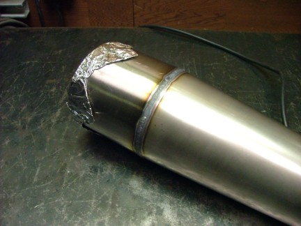
After finishing the jet pipe it was time to weld it to the v-band flange fitting. The flange was designed to fit over 5 exhaust tubing so it will overlap the jet pipe. This is a good thing as it can be lap joint welded which will help reduce warping from heat unlike a butt joint weld.
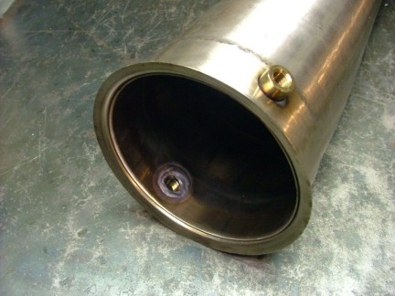
Once the weld was complete I wire brushed it clean and then touched it up on the belt sander. It was now time to install an 1/8 NPT SS threaded half coupling to hold the Auto Meter EGT probe I purchased earlier. I drilled a hole and welded the coupling from the inside of the jet pipe. I also installed a future sensor fitting into the opposite side if the jet pipe for good measure.
Note: The diameter of the turbine wheel (at the exducer) and the diameter of the jet pipe inlet should technically be the same with no changes in profile. This is to increase flow efficiency and reduce losses in power from turbulence and friction. The diameter of my jet pipe is about 1.35 larger than the turbine wheel because of how the turbos divergent exducer is designed. The expansion in profile may cause some power loss however it is hard to say how much without testing. It is my guess is that It will be minimal compared to the total thrust produced by the engine.
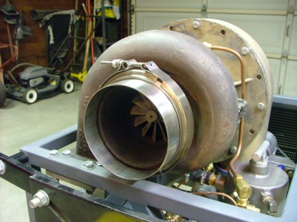
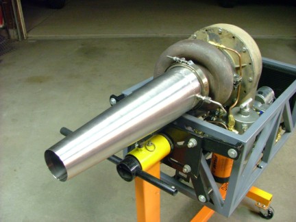
The jet pipe was complete! I bolted in the EGT sensor and clamped it to the VT-50 for a test fit. Man is stainless cool!!! I wonder what shade of blue this pipe will turn when I fire it up? :0)
The GR-7 is shaping up nicely. It wont be long before I find out if the engine can produce the 65+ pound static thrust goal I had set earlier. I still have a lot of developing left to do though. The starter system and ECU still need to be designed and built before I can start the testing process and fine tune the engines performance. The next project I plan to tackle is the starter system. I have been patiently waiting for the right time to start this phase of the build and I am really looking forward to it. I hope you can visit again to check out the next installment of the GR-7 Turbojet Project. Thanks for stopping by!!!