GR-7 Turbojet Engine Project 5/22/06

Posted on May 22, 2006

       It seems like it has been ages since I have had time to post an article on my progress with the GR-7. Other projects and commitments have pulled me away from the build despite my eagerness to finish the engine. Nevertheless, the GR-7 project must continue as there are still many things to learn. Luckily I have recently had some time between my responsibilities to develop more of the engine’s systems.

       One of my original goals for the GR-7 was to develop an electric direct drive starting system that would be capable of spooling up the VT-50 turbine. A system capable of engaging a starter motor directly to the turbine shaft and then disengage it from the turbine shaft once the engine is running. This would allow the operator to easily start the engine without any additional “ground support” equipment. Unfortunately developing such a starting system can be difficult as high speed rotating machinery demands precision tolerance and balance. Fortunately for me, I love a good challenge :0)
       Generally a turbocharger gas turbine needs to be spooled up to about 30% of it’s full operating RPM to self-sustain and successfully complete the starting cycle. This “self-sustaining” or “self-accelerating” RPM is where the turbine is capable of maintaining an idle speed under it’s own regenerative power. If the turbine does not reach this minimum RPM during startup it won’t be able to achieve the requirements for proper combustion and have a failed start.
       The GR-7 has a top RPM of 66,500 which would imply that it needs a starter capable of spooling it up to 20,000 RPM (30%). This will require a fairly high speed mechanical connection for any direct drive system to work. Not an easy task to accomplish considering that it must engage, spool up and disengage without damaging the hydrostatic bearings of the turbocharger. Any radial load to the turbine shaft while it is spinning could cause damage to the hydrostatic bearings or worse, cause the turbine wheel or compressor to “crash” into it’s housing at high speed.
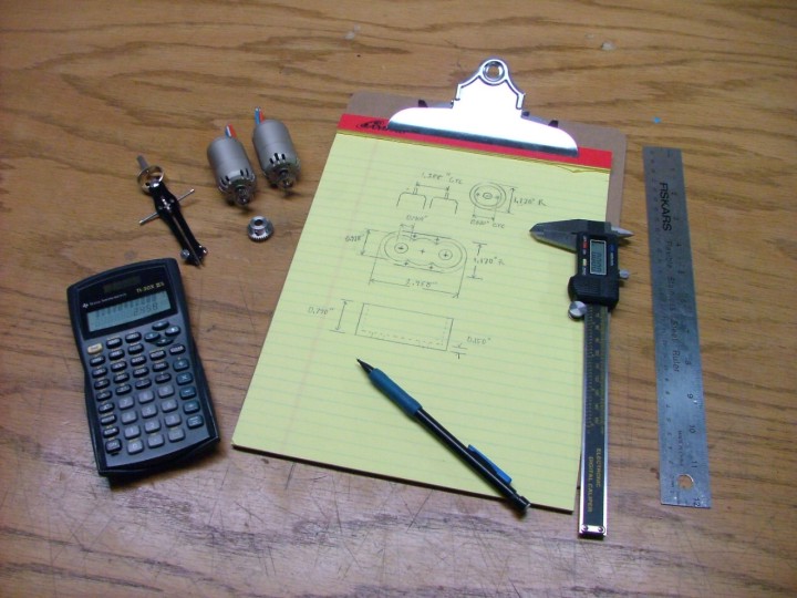
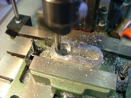
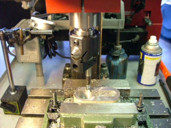
       I plan to experiment with a special hex-drive turbine coupling that will be properly aligned with the turbine shaft minimizing any radial load during startup. The hex-drive will ride on a retractable starter mainshaft and engage and disengage via a 12 volt solenoid. The starter mainshaft itself will be supported by two high speed bearings that will allow it to slide axially, making the turbine shaft/hex-drive connection possible (more on that later).
       To make my design work I will need a suitable electric motor to drive the starter shaft, capable of at least producing 3/4 to 1 HP @ 20,000 RPM. To find a possible candidate I started to search the internet. I discovered that a majority of the available high speed electric motors capable of this task are of a series wound, brushed variety. An example would be a electric die grinder or router motor. The series motor uses an electromagnetic armature field and stator field that are in a series connection which allows for incredible RPMs.
       Unfortunately the series wound motors that are readily available are bulky and require 120 volts AC to operate. This type of motor would be acceptable for a stationary engine but not really practical for a jet bike application. The series wound motor would need to be used with an on-board AC inverter capable of at least 1500 watts output which itself would be bulky. I needed to find a more practical motor system.
       I started to look into the brushless 3-phase motors used in remote control model applications as a possibility. Most are designed to be lightweight and produce incredible amounts of torque for their size. The “phasor” type motors use a rare earth magnets for armatures and utilize a poly phase type speed control to drive the stator fields during operation.
       Some phasor motors have internal armatures (for RC cars and small aircraft propellers) and some have external ones (for large, low RPM propellers). The internal armature variety are set up for high speed/low torque applications while the external produce low speed/high torque outputs. The external armature motors or “outrunner” motors are becoming more popular with the RC airplane crowd as they do not need a gearbox to increase slow speed torque for use with larger propellers.
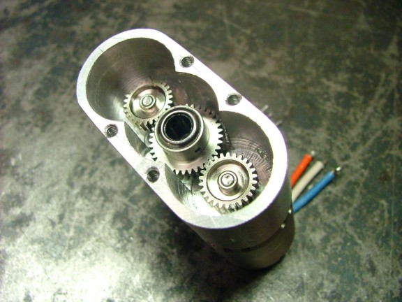
       Considering the weight savings as well as the torque output of theses motors convinced me that this was the type of motor I needed. I only had to decide what style and wattage motor I would use on the starter. I suspect that I will need around 500 to 750 watts of power to spin up the turbine with an output of 20 to 30K RPM. After weighing this information and factoring in the cost of the motors available I decided to use two small internal armature motors in leu of one larger one.
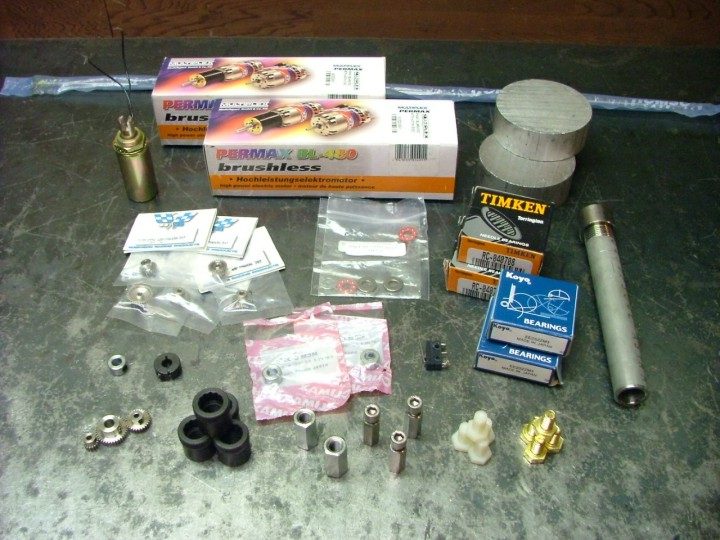
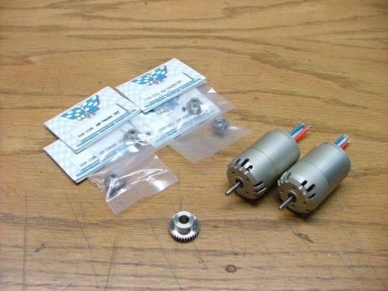
       The two-motor design will allow me to have a high RPM-high torque output from a relatively small package. The only drawback is that they will need to be coupled with a gearbox. I purchased a couple of Multiplex 480 size, 250+ watt 3-phase motors (#BL-480/5D) for the project. Supplied with 12 volts these motors can produce up to 32,000 RPM (45,000 max) without any problem. My only concern is will there be enough torque to start the engine?
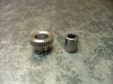
       To ensure I would have the most torque available I purchased some 48-pitch RC car pinion gears of assorted sizes to “fine tune” the motors gear ratio if needed. The larger 36 tooth spur gear below was purchased from
McMaster-Carr (#6832K44) and the RC car pinions from Tower Hobbies (#LXEX24).    

         I chose to start with 26 tooth pinion gears for the motors which when coupled to the 36 tooth main gear will produce a 1.38:1 ratio. I estimate that the motors will turn around 28,000 under load so the 1.38:1 ratio should drop the RPM to around the target RPM of 20,000. 

       I started to think about how I would couple the main gear to the starter shaft while allowing it to move in and out. I drew up a couple of ideas and settled on a design where the starter mainshaft is driven by a one-way needle bearing pressed into the main spur gear. When the gear is not driving the shaft it will allow the shaft to move axially. This will help me to couple and de-couple the turbine from the starter.

       To carry out my design I needed to machine a gearbox that would hold the motors as well as align the gears. I had purchased a couple of 3” X 1” 6061 aluminum discs earlier for this project and I hoped that I could machine the starter gearbox out of one of them. I had never machined such a part before so I was looking forward to learning what I could.
       I started out by boring a 1/4” “registration” hole in the center of the disc. This will allow me to reference my measurements to a non-changing location on the part.

       I then surfaced the disk to ensure proper mounting on the mill table.

       I decided to use an end mill to trim off the excess metal from the part to create the basic shape of the gearbox.

       To complete the next step I had to drill two more registration holes to mark the location of the motor’s shaft centers. These holes will help me center the part on the table for the upcoming machining steps.

       I proceeded to offset the gearbox part on the shaft centers to round out the corners of part. These holes helped me to align the part correctly on the rotary table.

       I had the basic gearbox shape down and was ready for the next step.        I now needed to mill out the portion where the gear train will be housed. To do this I set up my mill vise and aligned the part parallel to the travel of the mill table with a dial indicator.

       I proceeded to “plunge cut” the majority of metal from the part with a large end mill. This will help out the boring process that will create clearance for the gears. After I milled the hole I aligned the part to one of the motor shaft centers using a drill blank in the mill chuck.

       I decided to use a boring head to cut out the areas where the gears will be. This worked out very well and allowed me to size the holes very precisely.

       The boring process was repeated three times for the three gears used in the gearbox.

       I was now ready to drill and tap the gearbox cover screws. I carefully laid out the centers and then drilled them out with the mill. A hand tap was then used to thread the holes.

       I flipped over the gearbox and proceeded to drill out the holes for the motors including the motor mounting hardware holes.

       Note that the motor mounting holes are not at the same angle to each other. This is to compensate for the way the motors were manufactured, with the cases pressed together slightly different than each other. I wanted the motor leads to be at the same angle so I adjusted the hole layout a bit.

       I could now mount the motors for a test fit and see if my measurements were correct.

       Satisfied with the fit I was able to move on to the main spur gear modification. I needed to install a one-way needed bearing into the hub of the stainless main gear to facilitate a drive release when the turbine’s speed increases the motors ability to turn. If the turbine was allowed to overspeed the motors they could in turn destroy themselves. The one way bearing should eliminate that possibility.       

       I had to bore a larger hole into the gear to allow me to press-fit the bearing into it so I mounted it up into the lathe and started cutting. I piloted a hole slightly smaller than needed with a drill bit and then finished up the final cut with a carbide lathe bit. Notice the use of the lathe bit to “steady rest” the drill bit for a on-center cut.

       With the hole sized slightly smaller than the bearing I was able to press-fit the bearing into the center of the spur gear. Once I pressed the bearing in I was able to test out the bearing on the 1/4” precision hardened shaft I purchased to use as my starter mainshaft.

       I test fit the gears into the gearbox for the first time to see how they mated. I was hoping that there would not be any excessive space where the gears meshed and luckily it looked very promising :0)

       I am now “geared” up to tackle the next part of the build, the mainshaft tube and backplate assemblies. These parts will support the starter mainshaft and allow the solenoid to actuate the retractable starter coupling. Stay tuned for the next installment of the GR-7 project and thanks for visiting the site!!!

Till then...............

Don Giandomenico

[Home] [What's New At RCDON] [Articles] [Aircraft Projects] [Aircraft Videos] [Aircraft Videos II] [Experimental Projects] [GR-1 Turbojet Engine Project] [GR-5 Turboshaft Engine Project] [GR-5A Turboshaft Engine] [GRV-1 Turbotug Project] [GR-7 Turbojet Engine Project] [GRV-2 Jet Bike Project] [GR-6 Turboshaft Engine Project] [GR Engine Series Q&A] [Readers Projects] [Experimental Projects II] [My Collection] [RC Links] [About Myself] [Contact RCDON]