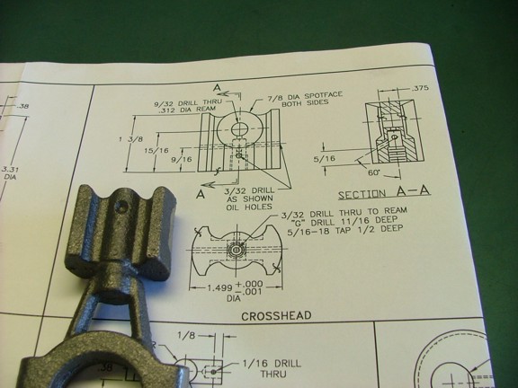
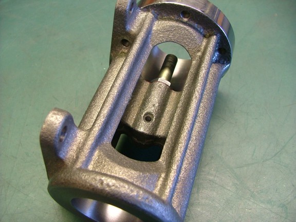
Hello again folks! This week I plan to tackle the crosshead which is a very important part of the 6CI engine. The crosshead takes all of the transverse force of the connecting rod and converts it into linear motion. This linear motion is important as the piston rod can have no side play or else the gland seal on the lower cylinder head will leak. Needless to say this part will need to be machined to precise tolerances or the engine will never run right.
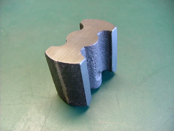
To start off I removed the eccentric yoke (or strap) from the crosshead casting with the bandsaw.
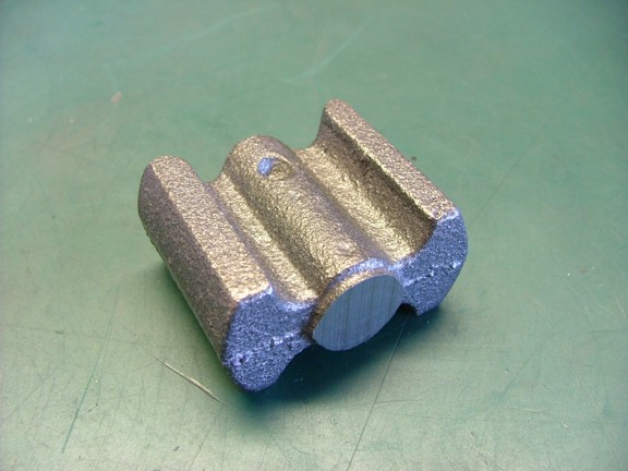
I decided to use my belt sander to clean up the casting before machining. This process is not quite as precise as milling but will get the job done fast. The rear face of the crosshead (the part that will attach to the piston rod) was ground flat first. I then cleaned up both sides of the casting so that they are .875 apart from each other (the two thin edges that are adjacent to the outer rounded faces). I made sure that the sides were parallel to each other as well as square to the rear face....
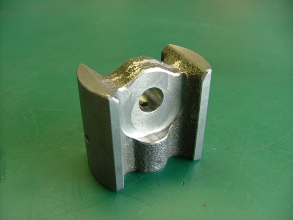
I drilled a location hole in the small casting dimple to later spot the depth of the piston rod bore (seen below). This dimple can be off a little so be careful to check the center of the hole from the two rounded sides.
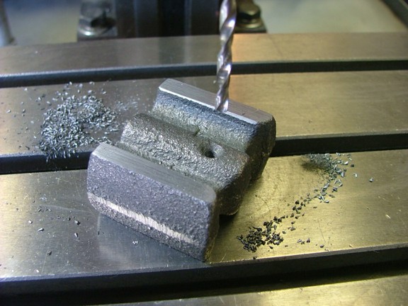
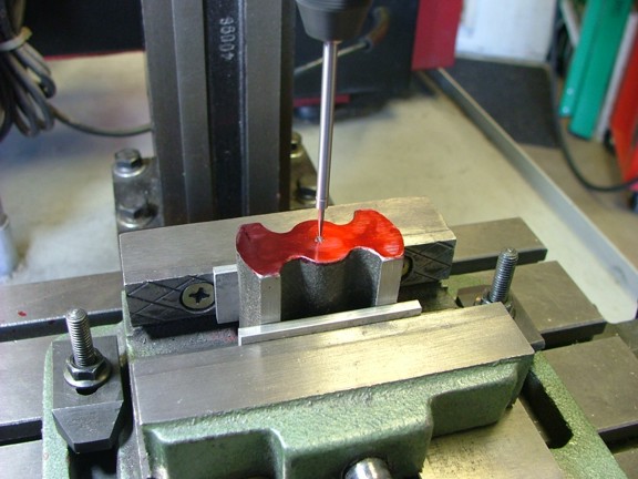
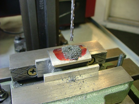
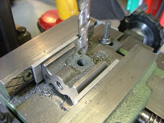
The next step was to drill the piston rod hole. I squared up the crosshead in the milling vise so that it was plumb and marked out my center of the casting. This center is the average of measurement from the outside edges of the round outer faces of the part. I used my center finder tool to center the mill on this mark to prepare for the drill. Notice the aluminum spacers on the sides of the crosshead. These spacers will keep the vises jaws from marring up the finished surfaces of the part.
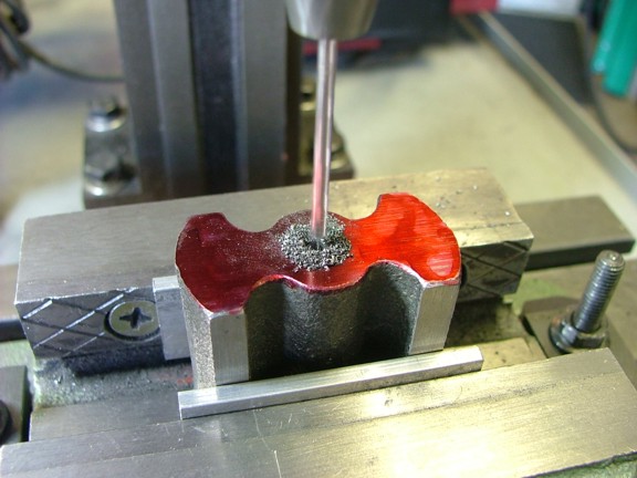
A 3/32 pilot hole was drilled first. I stopped the drill once it hit the wrist pin pilot hole I drilled earlier. This hole will be used as an oil passage to lubricate the wrist pin later on.
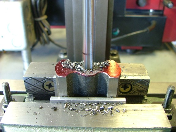
The next step was to drill a 1/4 hole for the piston rod threads (prints call for a size G drill - .2610 FYI) This hole only goes into the crosshead to about 5/8 deep.
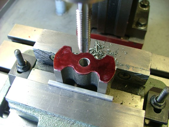
I used a 5/16-18 tap to thread the part while the crosshead was still centered on the mill. I used hand power to tap the part as my mill cannot turn that slow....
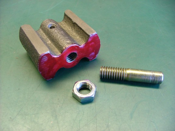
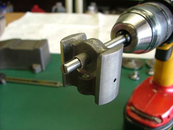
Now this next step is super critical! The crosshead must be machined super parallel to the piston rod or else the rod will bind in the gland seal. In other words, the engine will run very poorly if this is not done right!!! To make sure the crosshead is axially centered you must turn the outer faces around the threads of the piston rod. To do this I made a arbor out of a 5/16 bolt as seen below. This bolt will simulate the axis of the piston rod ensuring that the crosshead is perfectly centered on the rod. Of course the threads on the piston rod could be cut incorrectly (runout) and cause the same problem. Either way, axial alignment with the bore of the crosshead frame is super critical....
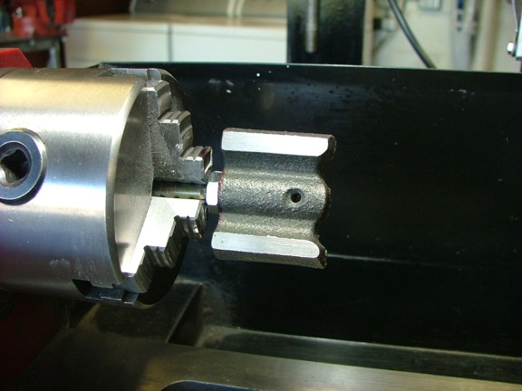
I mounted up the crosshead to the 5/16 mandrel bolt as seen below. I double checked the fit of the bolt to the lathes chuck to ensure a proper center before proceeding.
I cut the diameter of the crosshead to about .001 under the crosshead frame (or slide) bore for a tight fit. I periodically checked the fit of the crosshead into the frames bore as to not over cut the part.
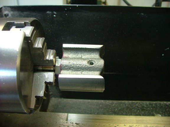
Once I was sure that the crosshead would fit into the bore I faced the end of the part as seen below...
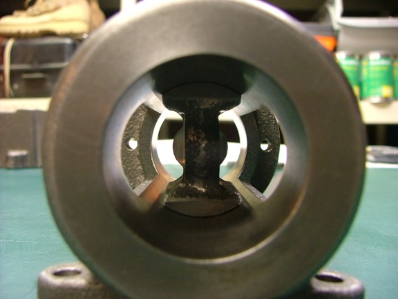
I removed the part from the lathe and checked the final fit. The crosshead fit perfectly into the bore!!! Only a couple of tight spots which will probably wear evenly when the engine is broken in. Note: I did not polish the crosshead as the rough machined surface will break in the frames bore quicker than if smooth. Kind of like a cylinder bore with piston rings....
The next step was to drill out the oil gallery holes in the crosshead. These holes will allow the frames drip oiler to pass oil to the wrist pin and lower crosshead guide.
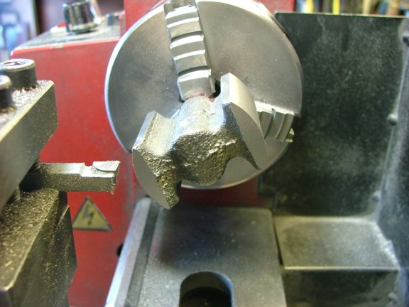
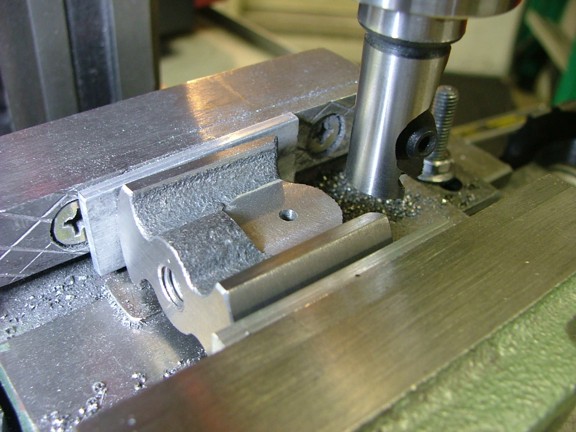
The next step was to mill out the connecting rod surfaces as to allow the rods yoke to fit over the end of the crosshead. It is important to make sure that the sides are evenly milled off of the center of the piston rod threads or the rod will be off center later on....
And now another fit check :0)
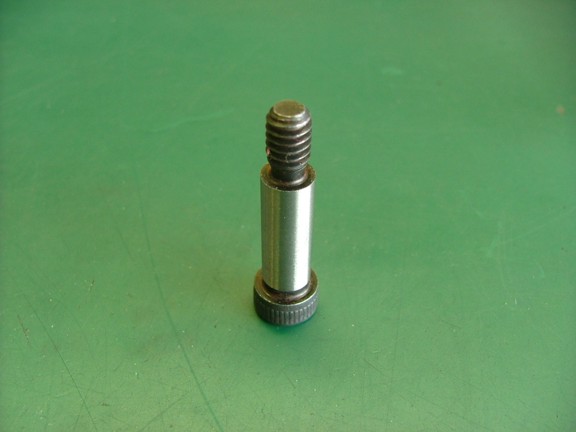
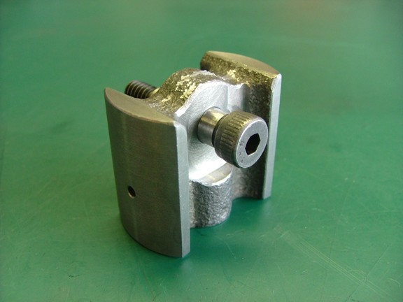
The wrist pin used in the kit is a piece of 3/8 hexagonal cold rolled steel that is to be machined into a shouldered bolt. I decided to forgo the machined bolt in lieu of a factory made, hardened steel bolt for the longevity of the engine. For this I will be using a 5/16 x 7/8 alloy steel shouldered bolt from McMaster-Carr (Cat #91259A582) as seen below...
I proceeded to drill out the crosshead with a 19/64 drill bit which is undersized for the wrist pin I had bought. My plan was to hone out the hole for a super close fit as to not allow any play in the bore.
Using my sandpaper/arbor method I was able to hone out the wrist pin hole to accept the pin very snugly. This is important or else the engine will knock loudly if there is any play in the linkage.
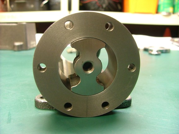
And now the finished part :0) I used a file to clean up all of the outer edges of the crosshead leaving what you see below. Notice the oil hole in the wrist pin bore...
Well another part has been finished and I am that much closer to the finish line. Join me again next time when I machine the connecting rod on the next episode of the 6CI project!!! Till then, always remember to wear your safety glasses when machining and always remove your chuck key before starting your lathe :oP