 |
 |
|
 |
|
 |
|
 |
|
 |
|
|
 |
|
 |
|
 |
|
|
|
Posted on May 16, 2011
Hello again everyone!! I am on the verge of testing my new boiler system on my 6CI steam engine. Until now I have been running my engine on compressed air but it just isn’t the same thing as live steam. The sights, sounds and smells of a live steam plant are alive with the spirit of human ingenuity. The rhythm of steam exhausting from the cylinder echoes the heartbeat of a engineering generation of long ago.
For about 30 years now I have dreamed of owning a “full scale” steam engine and now I get the chance to fulfill a childhood dream. Not only do I own the engine but I am responsible for a great majority of the machine work which has been a terrific learning tool for my machining skills. To finish off this build with a working steam boiler is quite satisfying and I can’t wait to get it plumbed into my engine!!!
|
|
|
 |
|
|
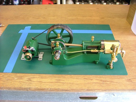
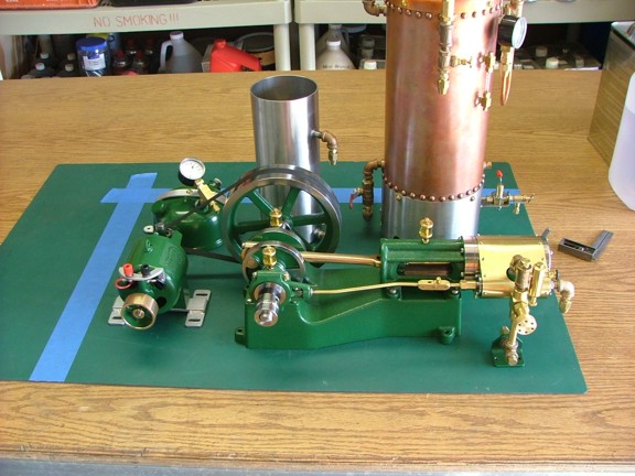
To get started with the pipe work I will need to mount the engine and boiler on the new “engine board”. This board will be made of 3/4” oak veneer plywood and will support the various engine components. To get an idea of where the parts will be mounted I framed out a square of cutting mat with some blue painter’s tape as seen below. This square represents the plywood engine base as it will be cut....
|
|
|
 |
|
|
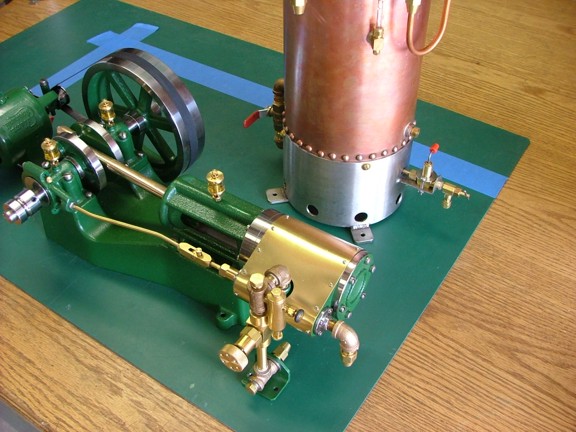
Careful positioning of the steam plants components is key at this stage as the pipe work will follow this layout. Moving the components later after the pipe work has been done will require a major reworking of the steam and water pipes....
|
|
|
 |
|
|
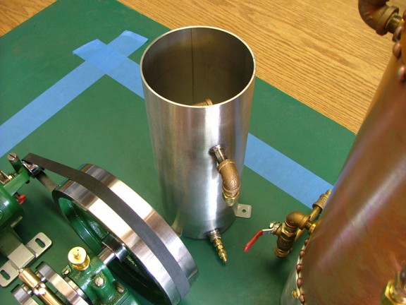
Careful thought was put into the accessibility of each component as well as serviceability......
|
|
|
 |
|
|
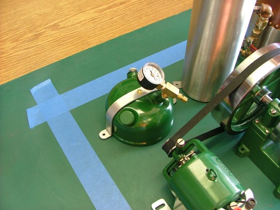
I positioned the feed water pump near the controls of the boiler as seen below......
|
|
|
 |
|
|
Once I was happy with the location of the steam plants components I was able to take detailed measurements of the mounting holes....
|
|
|
 |
|
|
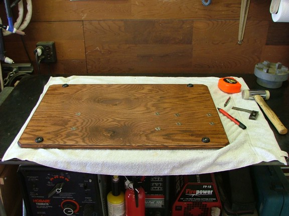
I cut out my engine board and placed several 10-24 blind nuts where the engine and generator were located. The board was also stained and sealed with a polyurethane sealer at this time......
|
|
|
 |
|
|
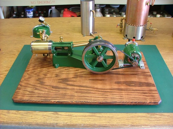
I mounted the engine and generator first......
|
|
|
 |
|
|
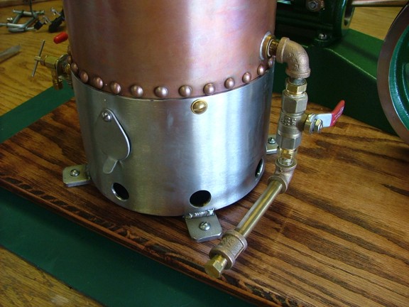
The boiler was mounted to the board with some #6 x 1” stainless steel wood screws as seen below...
|
|
|
 |
|
|
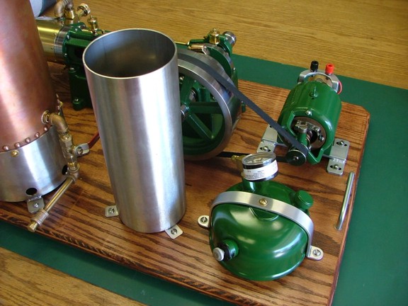
I followed suit with mounting the water tank and fuel tank.....
|
|
|
 |
|
|
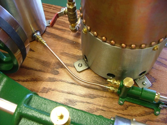
After I mounted the feed water pump I was able to start the pipe work. I installed the first 5/32” copper tube into previously installed tube union fittings making sure the bend and lengths were correct for the layout. I then used 4% silver solder to attach the tube to the union “cone ends”. Note: The water tank side of this tube uses an 1/8” NPT to 1/16” NPT reducer bushing to accommodate the 5/32” tube union. This bushing was fitted with a stainless steel screen to filter out any debris from the feed water (not shown).
|
|
|
 |
|
|
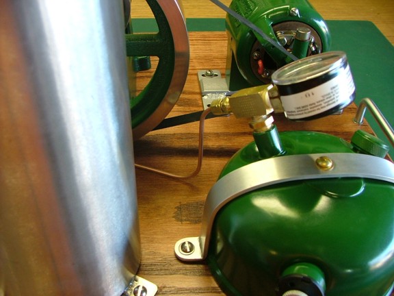
I made up the next tube to attach the pump to the tank and then soldered on the cone ends as seen below....
|
|
|
 |
|
|
The tube unions will make service work on the boiler much easier than screw-in type pipe. I will be able to remove the boiler in just a few minutes by removing a couple of jamb nuts....
|
|
|
 |
|
|
 |
|
|
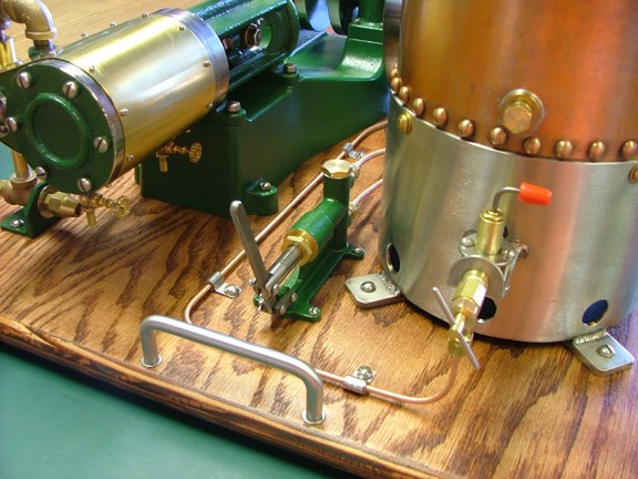
The next step was to plumb the 1/8” copper fuel line to the boiler.....
|
|
|
 |
|
|
I used some 1/4” stainless steel tubing straps along with some silicone tubing (used as bushings) to support the fuel line as seen below....
|
|
|
 |
|
|
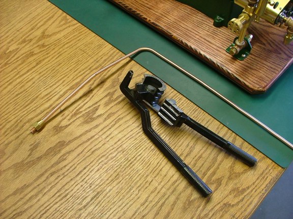
And now for the main steam line to the engine. I used 1/4” copper tubing to plumb this line which was much easier to work with than 1/8” NPT threaded pipe. The connections will be made with 45° flare fittings which offer the same convenience as the tube unions used on the 5/32” tube. A tubing bender was used to form the tube as seen below.....
|
|
|
 |
|
|
I wanted to use a larger bore tube for my exhaust pipe but failed to find any 5/16” tubing that was reasonably priced. I decided to use 1/4” for the exhaust as well which should work just fine considering how short the line is. The slightly higher back pressure may help with thermal efficiency by keeping the exhaust side a little warmer.
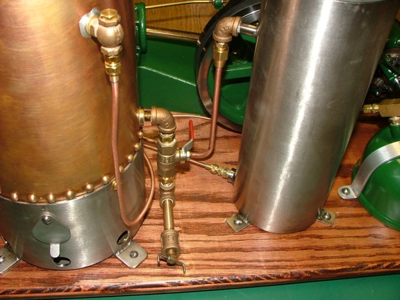
You will notice the pipe tee on the bottom of the throttle valve (below left). This tee will be used to blow-down the top of the boiler to remove oil and debris that may float on top of the water. The tee will also be used with compressed air to “dry up” the cylinder after each run. I can also connect a remote steam engine to this tee later on....
|
|
|
 |
|
|
 |
|
|
You will notice the lower blow-down valve and how it has a pipe plug in the down spout (below). This is to prevent any accidental discharge of steam/water from the boiler should the valve handle get bumped.....
|
|
|
 |
|
|
Having all of the necessary pipes in place it was time to see if the new feed water pump would work. I filled up the 1.25 quart water tank and primed the pump with a few pumps of the handle. I could hear the steel ball valves clacking away indicating that it was working.....
|
|
|
 |
|
|
The moment of truth was here and I could not wait to see if all this work would pay off!!! I topped off the boiler (1/2 gallon capacity) with distilled water (to avoid lime scale deposits) and closed off the main steam valve. The fuel tank was then filled up with 12 oz of Coleman fuel. I checked that my main fuel shutoff valve was closed and then pumped up the fuel tank to 25 PSI.
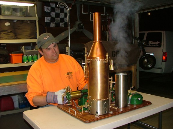
Using a lighter I held a flame over the burner through the firebox window and opened the fuel valve. Pooof!!! The burner was lit!!! Once the burner flame stabilized I pumped up the fuel tank to 35 PSI (which is the top end of the pressure range of this tank IMO). Within about 8 minutes I was up to 80 PSI steam pressure.
|
|
|
 |
|
|
I cracked open the main steam valve to pressurize the throttle manifold. I then opened up the two drain valves on the cylinder to bleed some steam through to preheat the cylinder. The throttle valve was opened and I waited till most of the condensation passed through the cylinder drain valve. I then opened up the displacement lubricator valve to get some oil flowing into the cylinder. I then pushed over the flywheel to see if the engine would tick over.
Immediately the engine sputtered and coughed condensation out of the exhaust pipe and into the water tank. At this point the engine was lumbering along and spitting out water through the drain valves. As the engine heated up the drains started producing white steam so I closed them and the engine cleaned right up. Within a couple of minutes the engine was up to operating temperature and ticking right along!!!
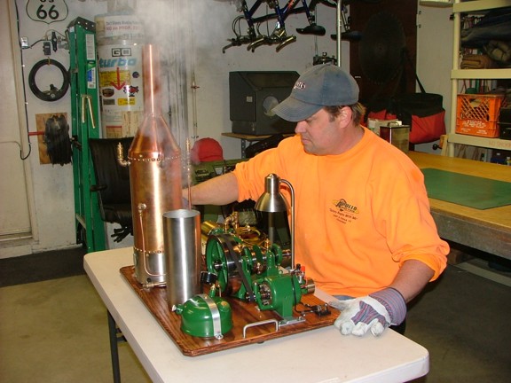
Note: You will notice the gloves. Yes I would suggest using gloves as it will probably reduce the burns you will endure to your hands and forearms. And yes I said reduce as you will more than likely forget that this stuff is hot and burn yourself once or twice like me :0/
|
|
|
 |
|
|
I closed the switch on the generator to put a load on the engine and it bogged it down to about 100 RPM. I adjusted the throttle to about 160 RPM which seemed to be a good pace for the engine and boiler. The boiler pressure was maintaining at about 80 PSI as long as the fuel tank was pressurized above 30 PSI. Although the fuel tank did not require constant attention it did need to be pumped every ten minutes or so to keep up the steam.
|
|
|
 |
|
|
I was paying attention to the water level in the boiler and was continually pumping the feed water pump to keep up. It became clear to me that an automated feed water pump would need to be devised at some point....
|
|
|
 |
|
|
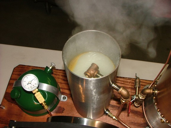
The water tank was working flawlessly at catching condensation as well as cylinder oil which floated on the top of the water (see above). Quite a bit of water was reclaimed as it condesated on the walls of the water tank.
|
|
|
 |
|
|
After about 40 minutes of run time it was time to refuel the boiler so I shut down the burner and released the tank pressure at the filler cap. After filling up the tank with 12 oz of fuel I was ready for more!! I refilled the displacement lubricator with steam oil at this point as well....
|
|
|
 |
|
|
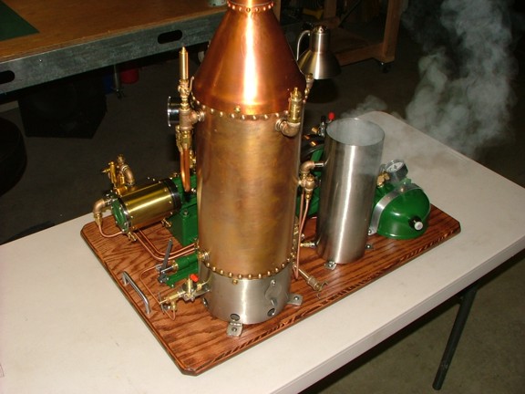
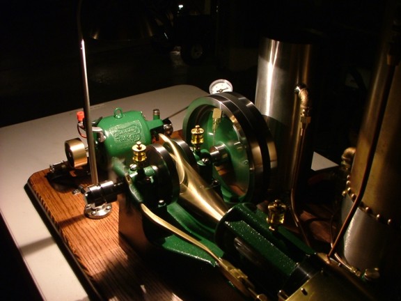
I could not get enough of the sound of the exhaust as it chugged away and of the smell of the steam oil. It was sort of like being in a time machine as you were witnessing an 18th century mining operation generator in action...
|
|
|
See the boiler demo video here!!!
|
|
|
 |
|
|
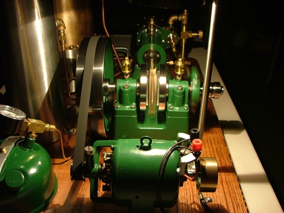
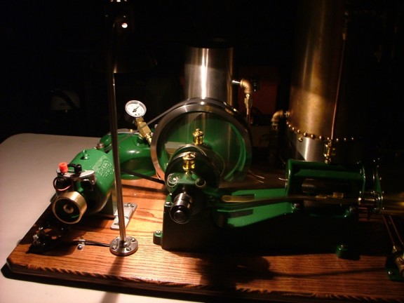
I turned out the lights and ran the engine for an hour of so with just the light of the lamp post. What an entertaining project!!!!
|
|
|
 |
|
|
 |
|
|
I thoroughly broke in the engine with about two gallons of water throughout the evening. I finally shut her down late in the evening taking care to drain out any water in the cylinder. I used compressed air to dry out the engine while it still was hot keeping the drain valves cracked open for a bit. I then forced cylinder oil into the throttle manifold with compressed air to coat the cylinder walls.
I tested the blow-down valve when the boiler was down to 10 PSI and released some steam/water. After the engine cooled down I cleaned up the oil puddles and then coated the bare cast iron with some Boeshield T-9.
|
|
|
 |
|
|
I thoroughly enjoyed this project and really cannot wait to run the engine again :0) Although I have now decided to build an engine driven feed water pump to relieve me of the burden of pumping in feed water every three minutes :0P
Join me again on the next episode where I build the new feed water pump to help automate the engine’s operation. Till then be safe my friends!!!
Don R. Giandomenico
|
|
|
 |
|
 |
|
 |
|