The LED Studio Light Project

<<< Previous Page

Next Page >>>

Page 5

       It was now time to start wiring up the driver trays. I installed Molex connectors on each tray to make them serviceable and modular as well. The drivers were grouped into two zones for each tray which included a single pilot driver and four main drivers. This was done so that the load can be sequenced to keep the inrush current of a simultaneous start from tripping a breaker.

       The power supplies and driver boards I am using utilize a technology called pulse width modulation to regulate or boost voltages. These pulses are set at a certain frequency and if they become momentarily in phase when first turned on that can cause a current spike. This current spike can cause the power supplies to overload and turn off which needs a solution.
       To fix this problem I decided to add a sequencing timer that is comprised of five programmable timers and associated power relays (seen below). These timers will introduce the load in a staggered pattern so that the light can reach full power without an overload.

       My plan was to make another tray out of the 3/16” GPO3 fiberglass board and mount it to the bottom of the light head. This location will make it easy to access the timers once the light is assembled.

       Since the timer relays can only handle a small amount of current they will need to be used with a larger 30 amp relay to switch the power on and off to the LED array.

       Molex connectors were made to connect the drivers to the power relays as well as spade connectors to attach to the relays themselves.

       Each timer board will control one relay which will in turn control four of the five LED chips in each bank. The fifth LED chip in each bank will turn on when the power supply is initially powered and serve as a pilot light while the associated sequencing timer counts down.

       Lots of wires to manage ;0)

       The light head is starting to look like a space station experiment.

       The next step was to wire up the control panel so that I could test the diode array.

       A Molex connector was used to make the control panel modular and removable from the light head for easy service access.

       After a final wiring check I was able to plug the light in and throw the switch. The power meter came to life and displayed the idle power draw of the control panel.

       I started to introduce the diode banks one by one to watch the current levels. So far so good!

       I briefly tuned on all of the diode banks to get a total current reading of 16.4 amps at 120 volts.

       I couldn’t leave the light on for too long as it would overheat in a matter of a minute or two without a cooling fan.

       Now that I had power to the light head I was able to set the sequencing timers. They were set with a one second delay from each other starting with timer #1 at one second, timer #2 at two seconds and so on.

       To be able to run the light continuously I will need active cooling. This will be provided by the cooling fan which was the next item to be wired up.

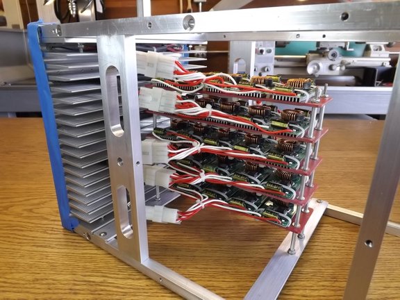
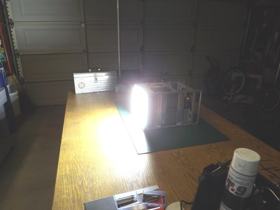
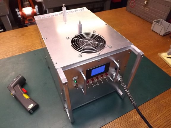
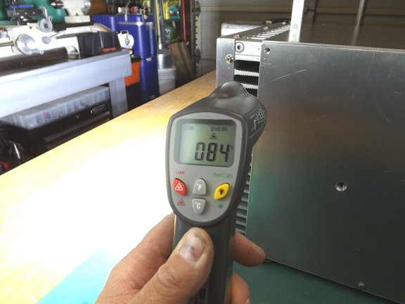
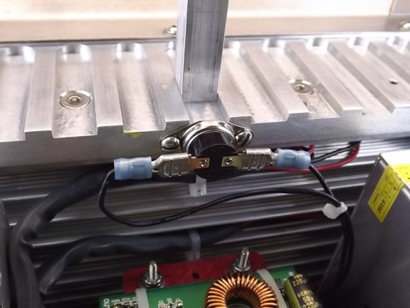
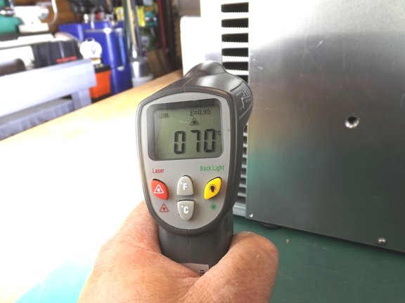
       I fired up the cooling fan and started a series of heat tests to see if the heat sink will be able to keep the chips cool enough. Using a infrared thermometer I was able to track the heat over a series of 15 minute runs. The ambient temperature of the garage was 24° Celsius when I turned the light on and the heat would stabilize at 84° near the center of the heat sink which is way too hot (183° F).
       The manufacturer of the chips suggested cooling to be held under 60° to achieve the maximum life span of 50,000 hours. I am no where near that which is a big problem. I probably would only get a few hours at this temperature before I started losing diodes.

       I had bet the farm that this heat sink was big enough to remove the waste heat and my only option at this point was to move more air past the fins of the heat sink. The single fan moved quite a bit of air so it was surprising that it could not do the job. A second fan would need to be added to help remove the hot air and fix this issue.

       Luckily I had left some room to accommodate a second fan which was shoehorned into the space below the carry handle.

       Because I am now so heavily dependent on airflow to keep from overheating I opted to install a thermal switch on the upper header block. The switch will remove power from the power relays should the temperature exceed 80° C. This fail safe switch will protect the array should a fan malfunction, ambient temperature be too high or the air flow be blocked somehow.

       I put the light head back together a prepared for another heat test...

       I powered up the light head once more and logged the heat rise over a 30 minute period. The highest temperature I could get with the infrared temp gun was 70° Celsius which is way better than it was before. The LED chips will work at 70° but at 93% light output over a chip run at 40°. Chances are that life span will be shorter than chip run at 40° but that’s the price I will pay for a compact array.
       Later on I would widen out the air outlet slots on the light head side sheeting to achieve a 4° C decrease in temperature which helped a lot (not shown).

       After the light head acclimated at full temperature I was able to observe the overall current reading of the meter on the control panel which I verified with an external ammeter. It seems that as the thermal junction of the diodes gets hotter the resistance gets higher and thus reduces power consumption.

       The light is performing well at this point and I must admit a bit brighter than I could imagine. You can feel the heat on your hands much like bright sunlight and I can only wonder what levels of UV light is emitted from this thing. It is not possible to look directly at the array as it is much like looking into the sun!!! I did try using welders goggles which helped confirm that all of the 1,250 individual diodes were working but was unable to get a picture of that.

<<< Previous Page

Next Page >>>

[Home] [What's New At RCDON] [Articles] [Aircraft Projects] [Aircraft Videos] [Aircraft Videos II] [Experimental Projects] [Experimental Projects II] [Nixie Tube Clock Project] [6CI Steam Engine Project] [Vertical Boiler Project] [The Toolroom Tune-Up Project] [The Reverse Tumbler Project] [Red Wing Engine Project] [MakerGear M2 Project] [The LED Studio Light Project] [My Collection] [RC Links] [About Myself] [Contact RCDON]