Sears Custom 10XL Project

<<< Previous Page

Next Page >>>

Page 2

       I decided to use my angle grinder/cut-off wheel method to reshape the tooth profile on the cast gear to allow for more engagement with the pinion bevel gear. I mostly eyeballed the process which should be good enough for the precision required ;0)

       I added about a 1/16” depth to the root of the gear profile which should do the trick.

       The next step was to fix the e-clip groove in the steering shaft...

       A nice 1/16” wide HSS parting tool was used to regroove the shaft (after the bad end was cut down - not shown).

       I removed the instrument panel of the tractor to install the steering column and revealed some acid damage to the chassis. Luckily it wont be exposed when the dash is back in place.

       The big gear fit back into place and ready for fitting of the pinion...

       I reinstalled the dash to align the shaft geometry and fit the steering wheel to set up gear/wheel position.

       The steering column tube has adjustment slots for the hardware to adjust the lash. I set the lash as well as adding some spacers (not shown) to raise the pinion to best match the big gear.

       The gears now mesh really well with only a few tight spots of which I fine tuned with the grinder for smooth action all the way through...

       The next step was to work on the axle beam which had a broken guide bushing. You can see in the photo below how a groove was worn into the beam from the frame.

       The beam itself also had a few bends in it which needed to be worked out.

       I used my 6 ton press to smooth out the bends which it did effortlessly...

       The next step was to reweld the bushing onto the beam...

       To prevent further cracking I added a gusset and piled on way to much weld :0/ I’m a bit rusty myself.

       A quick test fit...

       I decided to add a couple of angle iron wear surfaces or “bumpers” to the inside of the frame to prevent the beam from further damage.

       Both sides of the beam receiver now have a wide wear surface.

       The spindles were in good shape other than a bent control arm on one. Easily straightened out...

       I installed new roll pins on the axles and they were ready for the axle beam.

       You can see a better view of the angle iron “bumpers” I welded into place below...

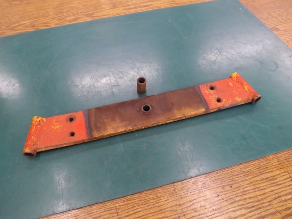
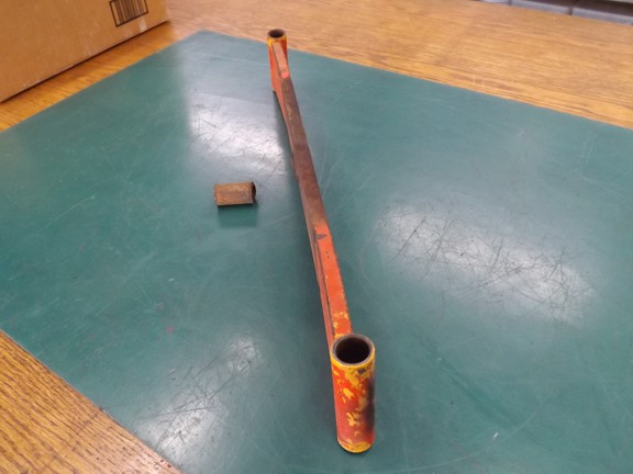
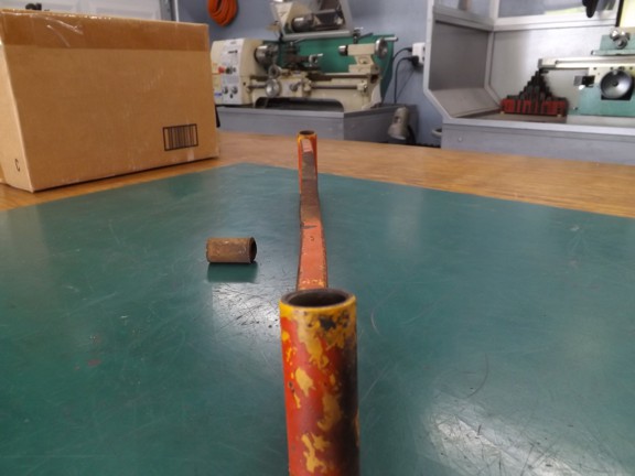
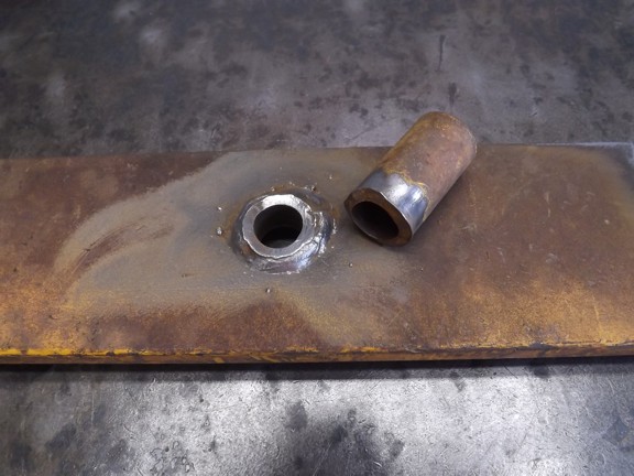
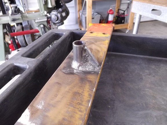
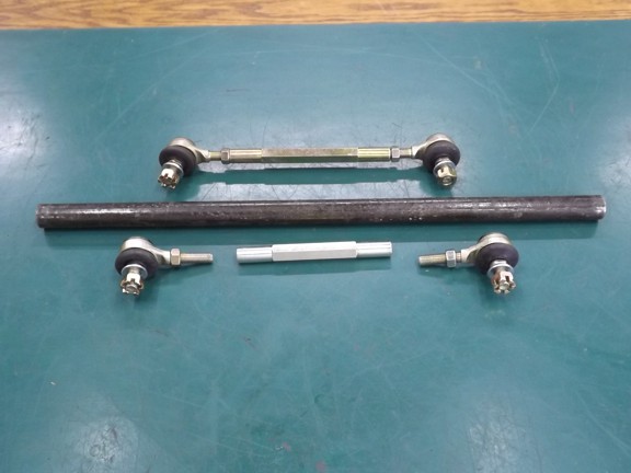
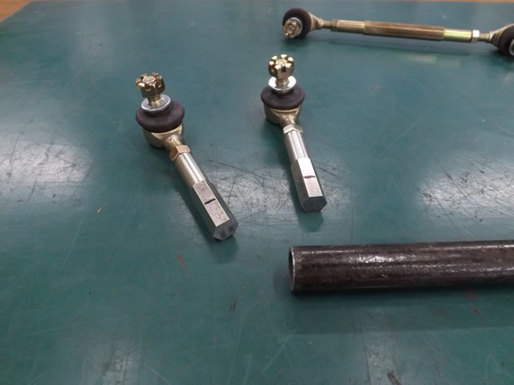
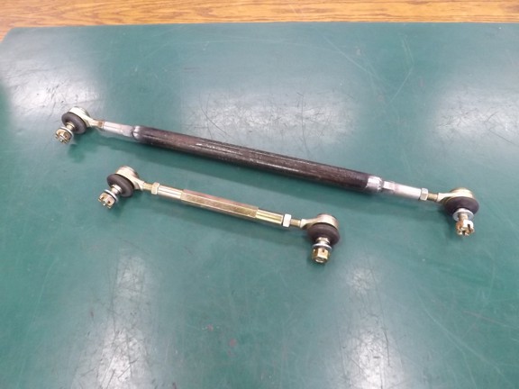
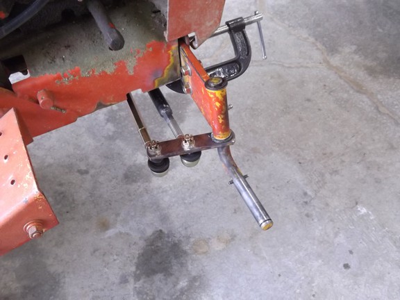
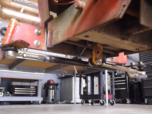
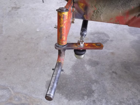
       The original tie rods were trash and needed to be replaced. I found some cheap ATV tie rods ($16 each) on Amazon that would do the trick. One of the rods would need to be lengthened for the relay rod of which I used a piece of 1/2” schedule 40 black pipe to make a rod extension.

       I cut the existing short rod and welded it into the pipe as seen below...

       I fit the new tie rods into place and adjusted them for even spindle movement. Making progress!!!

<<< Previous Page

Next Page >>>

[Home] [What's New At RCDON] [Articles] [Aircraft Projects] [Aircraft Videos] [Aircraft Videos II] [Experimental Projects] [Experimental Projects II] [Nixie Tube Clock Project] [6CI Steam Engine Project] [Vertical Boiler Project] [The Toolroom Tune-Up Project] [The Reverse Tumbler Project] [Red Wing Engine Project] [MakerGear M2 Project] [The LED Studio Light Project] [Sears Custom 10XL Project] [My Collection] [RC Links] [About Myself] [Contact RCDON]