 |
 |
 |
|
 |
|
 |
|
 |
 |
|
 |
|
|
|
 |
|
 |
|
 |
|
|
|
Posted on August 20, 2012:
Time to get back at it ;0) I now need to drill and tap the 8-32 holes for the four set screws in each flywheel. I laid out the four locations and center punched them for ease of drilling.
|
|
|
 |
|
|
These don’t need to be super critical in location so I freehand the holes with a #29 drill...
|
|
|
 |
|
|
And now the tap...
|
|
|
 |
|
|
The set screws that come with the basic Red Wing kit have a cupped point and I don’t want my finished crank to get scarred up so I used my belt sander to sand off the cup (seen below).
|
|
|
 |
|
|
I mounted the first wheel to the turning arbor to finish turning the hub as I had before on the other side.
|
|
|
 |
|
|
I cut down the hub using the same measurement as before...
|
|
|
 |
|
|
And now for the radius cut...
|
|
|
 |
|
|
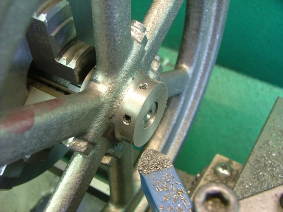
The finished product :0)
|
|
|
 |
|
|
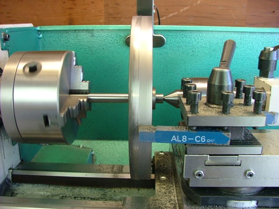
I moved the turning arbor out of the chuck and used the tail stock to support the far end as seen below. This will eliminate some of the runout that the scroll chuck inherently has in it at smaller diameters. I started cutting down the OD at 40 RPM...
|
|
|
 |
|
|
Luckily there was very little harmonic vibration at this speed...
|
|
|
 |
|
|
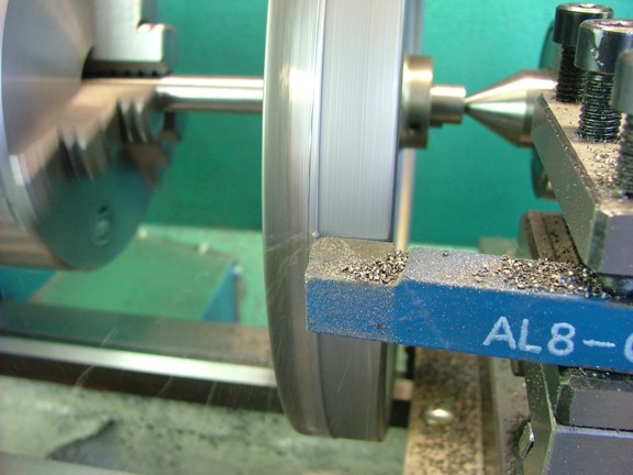
The tool bit had to be sharpened on a silicon carbide grinding wheel several times as the rough casting surface still has some sand embedded in it. Once I got through the surface it was smooth sailing.
|
|
|
 |
|
|
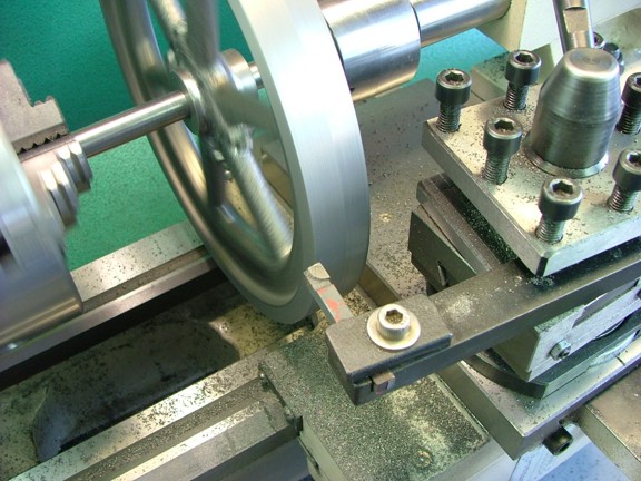
I turned down the OD to about 8.235” which is a little bigger than the scale size of 8”. I then moved to the outside faces using a tool bit holder that I made for my 6CI steam engine build. This tool allows me to get the backside of the wheel without flipping it over.
|
|
|
 |
|
|
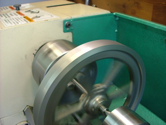
The next step is to bevel the inside edge of the wheel (optional) to give the border an even appearance. I just took off enough material to even out the edge...
|
|
|
 |
|
|
The wheel is looking good now...
|
|
|
 |
|
|
I decided to blend in the bevel cut with my Dremel tool as seen below.
|
|
|
 |
|
|
And now to polish. I experimented with several methods of smoothing out the cast surface and settled on using diamond hones. The hones make quick work of grinding out the cut lines and leave the best possible surface for polishing IMO.
|
|
|
 |
|
|
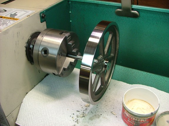
I followed the hones with a little 320 grit sandpaper and then polished the wheel with some Mothers wheel polish. I polished the hubs at this time as well...
|
|
|
 |
|
|
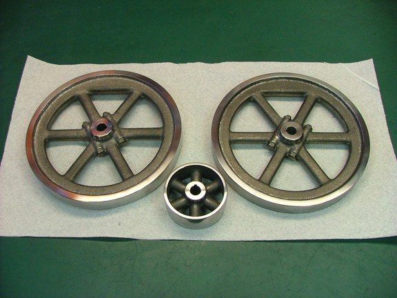
I repeated the process with the other wheel (not shown).
|
|
|
 |
|
|
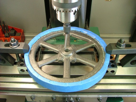
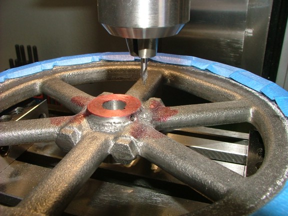
The next step is to machine the slots for the governor weight arms. I mounted the wheel on the mill table (notice the blue tape protecting the polish) and found the center of the bore with the wiggler tool. I set up the wiggler with a point probe and offset the needle so it touches one side of the bore. I then manually turn the spindle to the other side and tap the needle with my finger. I do this multiple times in all four directions.
If the needle moves outward I move the table in the opposite direction in increments until I cannot get any movement from the needle in both axis. Sounds complicated but it isn’t. It just takes practice.
|
|
|
 |
|
|
I zeroed out the table on center and then moved the table over .670”. I then used a #2 center drill to spot the slot ends on the hub.
|
|
|
 |
|
|
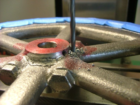
A 9/64” drill bit was used to chase the center drill through the hub as seen below on both sides of the hub...
|
|
|
 |
|
|
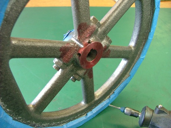
I milled out the rest of the slot by hand with my Dremel tool. I used a carbide rasp and with some patience I completed the task.
|
|
|
 |
|
|
 |
|
|
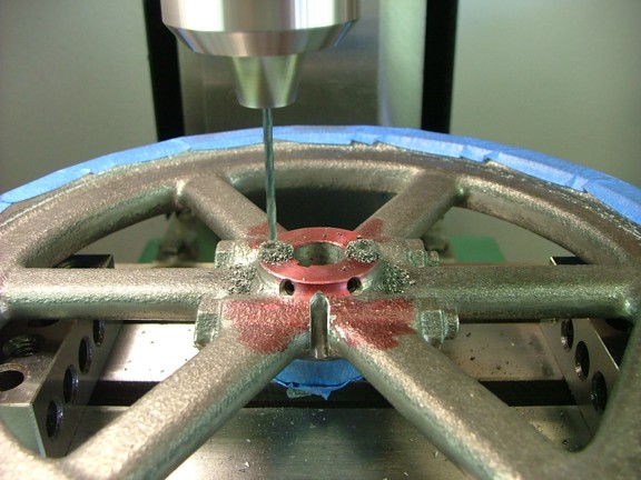
The next step is to drill and tap the holes for the governor arm bracket screws. I found the center of the hub (not shown) and offset the table .4375” (radius) to drill out two #43 holes at .375” deep on both sides.
|
|
|
 |
|
|
I tapped the holes with a 4-40 hand tap using my 3/8” chuck method.
|
|
|
 |
|
|
The flywheels are now complete so I can move on to the last cast iron casting in the kit which are the muffler castings.
|
|
|
 |
|
|
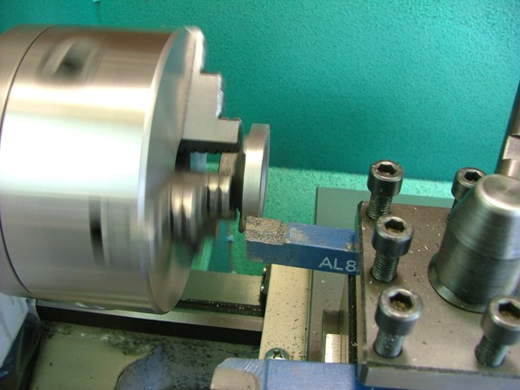
I mounted up the back side of the “ball” muffler and turned the OD down to 1.9”.
|
|
|
 |
|
|
I now faced the inside so that the edges were .125” thick as the prints suggest.
|
|
|
 |
|
|
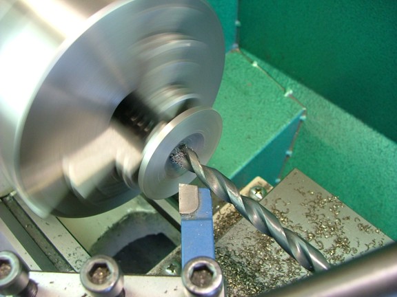
I now used a 11/32” drill to bore out the center for the 1/8” NPT threads that will be tapped later.
|
|
|
 |
|
|
I moved the inside casting over to the mill and mounted it in a three-jaw chuck up on my rotary table. I set the part up on two parallels to give some space from the chuck face as seen below.
|
|
|
 |
|
|
I found the center with the wiggler tool and zeroed out the table...
|
|
|
 |
|
|
I now used a 1/8-27 NPT tap to make the threads as seen below.
|
|
|
 |
|
|
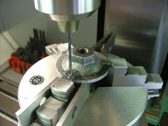
I moved out the table .8125” (radius) to drill out the muffler screw holes and drilled them with a #38 drill at 120° apart (using the rotary table to index the part).
|
|
|
 |
|
|
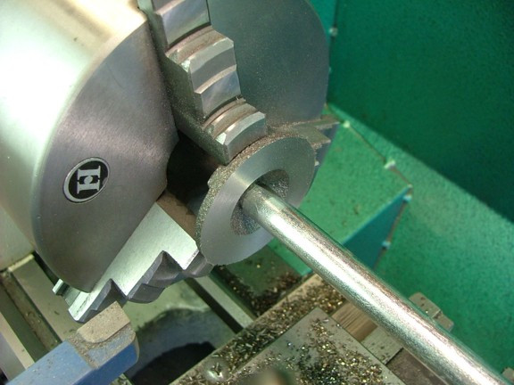
The next step is to machine the outer half. I used a steel rod to “pin” the half to the chuck jaws using the tailstock as seen below.
|
|
|
 |
|
|
 |
|
|
I machined the face down to .125” at the edge as before...
|
|
|
 |
|
|
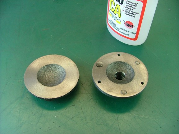
The two halves were now glued together with some Cyanoacrylate glue for the next step.
|
|
|
 |
|
|
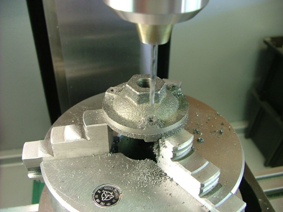
I used the first set of #38 holes as a drill guide to drill through the second half.
|
|
|
 |
|
|
I split the muffler halves with a little heat from my torch (not shown) and then tapped the holes in the outside half with a 5-40 tap...
|
|
|
 |
|
|
And now to drill out the inside half with a #30 drill bit so the screws will fit.
|
|
|
 |
|
|
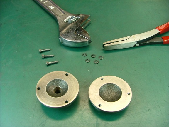
Using the 5-40 “bolts” provided in the Red Wing hardware kit I mounted the two halves together. I added some split washers to space the halves apart as seen below.
|
|
|
 |
|
|
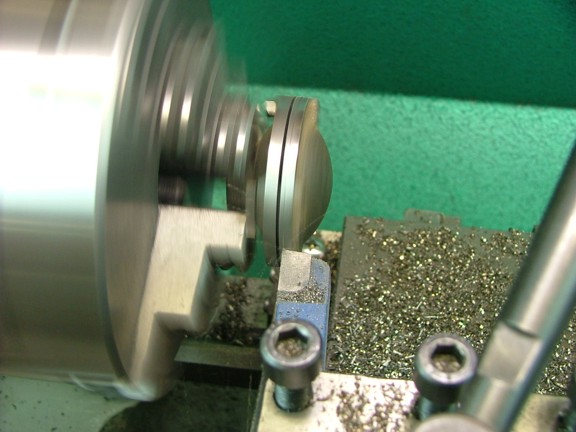
I now could turn down both sides of the muffler to a diameter of 1.875”.
|
|
|
 |
|
|
And now to add the spilt washers that were provided in the basic kit. I am a big fan of using washers however I don’t care for what split washers do to a finished surface should you need to remove the screws later on. This is why I like to flatten out the spring of the washer to eliminate their destructive force ;0) I will be using locktite on most of my screws and bolts anyhow...
|
|
|
 |
|
|
And now for the final fit. I assembled the finished muffler and then used a center punch to identify the assembly orientation to ensure a perfect fit later on.
|
|
|
 |
|
|
I am making great headway now so please check back soon for the next episode of the Red Wing project!!!
Take care,
Don R. Giandomenico
|
|
|
 |
|
 |
|
 |
|