 |
|
|
|
|
|
|
|
|
 |
|
|
 |
|
 |
|
|
|
Posted on October 27, 2012:
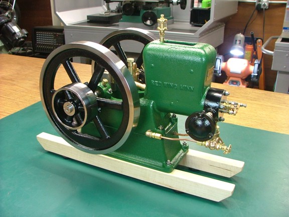
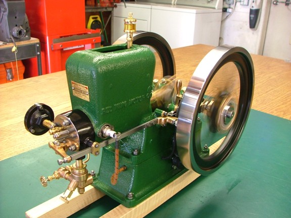
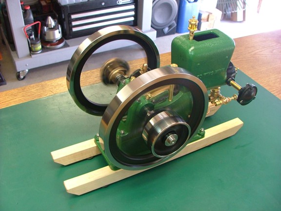
Hello again everyone! I have been patiently waiting for the paint to cure on my new engine so that I can run it for the first time. I have allowed a few extra days of curing before getting oil on the new acrylic paint. Now that the paint is good I can fuel her up and see what happens!!!
|
|
|
 |
|
|
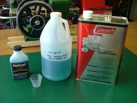
To get the Red Wing engine running I will need some fuel so I did some research on what fuel works best for model hit and miss engines. It seems that most modelers use Coleman camping fuel as it does not smell bad like gasoline and does not gum up fuel systems when stored for a long time. Coleman fuel has an octane rating of 50-55 which much lower than gasoline which can cause pre-ignition in high compression engines. Luckily this is not much of a problem for these low compression model engines.
Most modelers mix their Coleman fuel with 5 to 10% of WD-40 lubricant which is supposed to help flush out carbon deposits as the engine runs. I like the idea of running a little lubricating oil in the fuel but I really dislike WD-40 so I am going to add some National 2-cycle engine oil to my Coleman fuel which will help lubricate the rings and valves as well as reduce carbon buildup.
I mixed a 40:1 fuel to oil ratio in a half gallon jug (seen below) to fuel my new engine.
|
|
|
 |
|
|
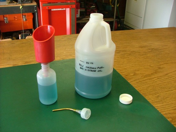
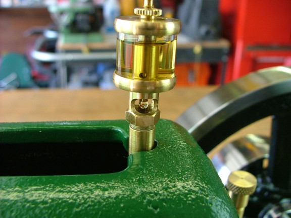
I purchased a 6 oz squeeze bottle (McMaster-Carr Cat# 4176T3) and modified it with a brass tube to fit into the filler neck of the engine (seen below). I then filled the bottle with my 40:1 fuel mix using a Coleman filter funnel (Cat# 5103A700T). Note: It is a good idea to always filter the fuel especially if it has been sitting in the jug for a while. Small sediments can clog the fuel system very easily making for a rough running engine...
|
|
|
 |
|
|
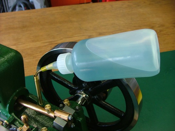
The onboard tank takes about 4.5 oz of fuel before overflowing so take care to not fill the tank too fast. I found that wrapping the filler neck with a rag will prevent fuel from spilling on the engine when topping off the tank (not shown)...
|
|
|
 |
|
|
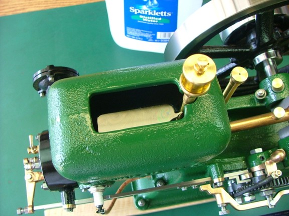
I filled the water hopper with some distilled water to help aid in cooling the engine. The water will remove heat from the engine through evaporation as the cylinder temperature rises...
|
|
|
 |
|
|
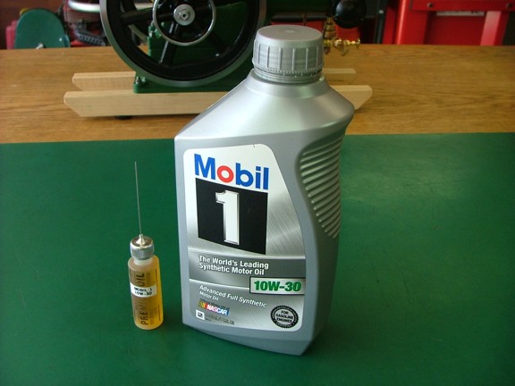
I now needed to find a lubricating oil for my new engine. I normally use a synthetic SAE 20 weight hobby oil to lubricate my model engines however the stuff I use is quite expensive in volume. I decided to find a cheaper substitute and after some research I purchased some Mobil-1 10W-30 synthetic oil. This stuff is perfect for use in model drip oilers and its detergent additives will clean out carbon deposits in the cylinder as it flows out of the cylinder.
I filled up an empty needle oiler bottle (seen below) with my new oil and I was ready to go...
Note: Mobil-1 is a detergent style motor oil which some would object to using outside of a filtered circulating oil system. This is because the detergent additive causes contaminants to be suspended in the oil instead on on the bearing surfaces. This would make some to think that this would promote more wear than if the dirt was to stay in place on the bearing surface.
I personally believe that it is better to use a detergent oil when used for an application that produces waste oil runnoff. This is because the oil is continually being purged out of the bearings and not reused which carries away contaminants as opposed to leaving them in place. This of course would not be the case as with an enclosed gearbox where the oil is allowed to recirculate unfiltered. Just my two cents ;0)
|
|
|
 |
|
|
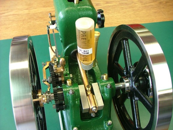
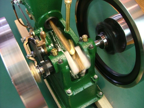
I filled up all three grease cups with the Mobil-1 as well as the drip oiler for the first run. I also oiled all of the metal to metal friction points including the wrist pin, shift collar, governor weights, latch out bar, pushrod, rocker arm, valve stems, timing gears and bushings.
|
|
|
 |
|
|
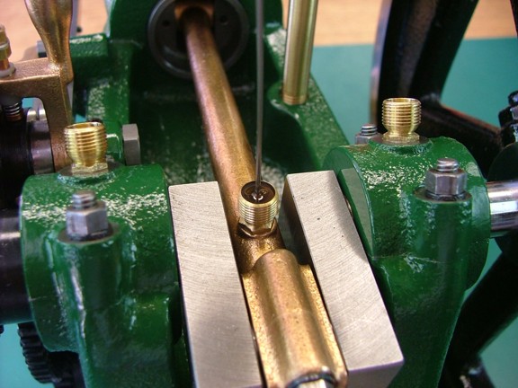
The grease cups work perfectly with the needle oiler as it can fill the cup from the bottom up which will purge out any air in the system.
Addendum 10/15/16:
I have since started using Super Lube synthetic grease (Cat #21030) on all of my grease cup applications which works beautifully. I just dab a bit in the removed cup and screw it down on the threads. It hydraulically fills the bearing with just the right amount of grease for each run of the engine...
|
|
|
 |
|
|
I set up the drip oiler so that it drips one drop every two minutes which is plenty of oil considering the fuel has oil in it as well.
|
|
|
 |
|
|
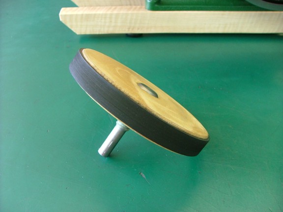
To start the engine I decided to build a starter wheel which can be put in a cordless drill. This wooden wheel was made out of a 4.5 diameter piece of 3/4 thick plywood that is mounted on a 1/2 arbor bolt. A Hoover Vacuum cleaner belt (Cat# 38528-033) was glued on to the wheel with Cyanoacrylate glue (Krazy Glue) to easily grip the flywheel of the engine.
Note: The starter wheel may not be necessary later on although it will help me start the engine before the mixer is dialed in.
|
|
|
 |
|
|
The moment of truth was at hand!!! I opened the main fuel valve and set the needle valve to one turn out from the bottom. I then spun up the flywheel with my starter wheel (and cordless drill) to start the engine...
|
|
|
 |
|
|
The engine popped and sputtered but did not maintain running so I turned in the needle valve in increments until the engine would stay running (about a 1/4 turn out). The Red Wing engine was now running for the first time!!!
|
|
|
 |
|
|
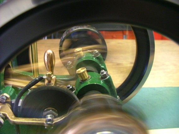
The governor had not been set so the engine was running at about 750 RPM which is a bit high for this model. The timing gears were somewhat quiet however the magneto was indeed causing gear chatter as I suspected it would. I continued to let the engine run for a few minutes to warm up and to allow the rings to seat correctly in the cylinder...
|
|
|
 |
|
|
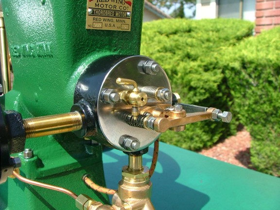
I stopped the engine and adjusted the governor so that the engines speed was at 600 RPM and then run the engine for an hour to somewhat break in. Unfortunately the magneto was causing the timing gears to sound like a Ford Powerstroke diesel at idle :0P The engines lower speed increased the effect of the magnetos push and pull on the timing gears which did not get quieter with time :0/ It became evident that this was a problem I would have to deal with.
Note: The engine will run as slow as 450 RPM with the Falcon magneto setup however the engine does not have the power to recover from instantaneous loads applied to the pulley. I have discovered through experimentation that the engine will run best at 550-600 RPM if it is to be used with a mechanical load. I set my engine RPM with a laser tachometer and then fixed the governor adjustment nuts with blue Locktite (not shown)...
|
|
|
 |
|
|
I tried to fix the gear chatter problem by swapping out the idler gear with a nylon gear to absorb some of the mechanical noise (not shown). Unfortunately the gear did very little to reduce the noise so I abandoned that idea. I then researched using anti-backlash gears which would be expensive and require me to re-engineer the whole system. I even tried heavy grease on the gears which worked fairly well until the grease flung everywhere :0/
Finally I decided on a friction brake system that would apply an even load on the timing gears and keep them from chattering. This would be the easiest fix and would require only a small modification to the engine to install. The only drawback to a friction brake is that it will apply an additional load to the engine but hopefully it will be small enough to not effect the coast duration of the hit and miss cycle.
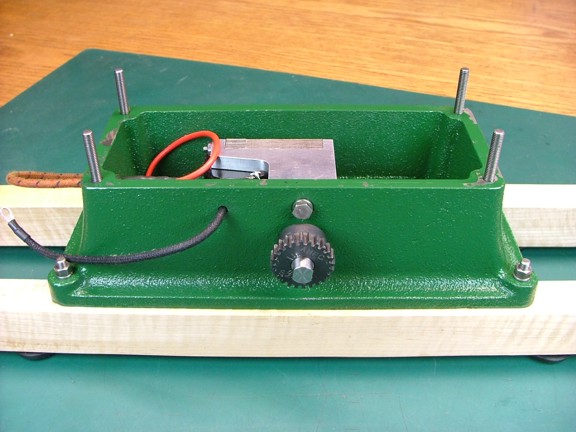
To start my modification I removed the engine frame from the base and started taking some measurements. Note: The coast duration is what I call the number of revolutions the flywheel will spin before a combustion cycle will fire to maintain engine speed...
|
|
|
 |
|
|
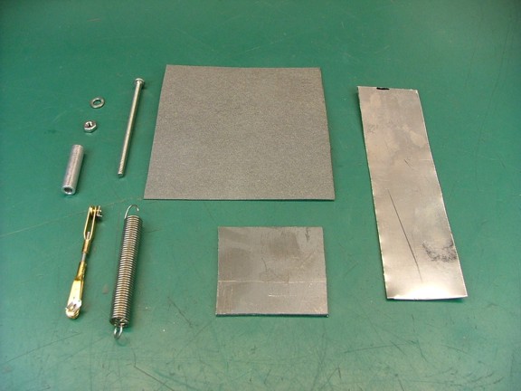
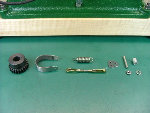
I gathered together several items (seen below) including some .031 thick high-temp gasket material (Mr. Gasket Cat# 9611), .018 thick 304 stainless steel steel sheet, .060 thick mild steel plate, 6-32 machine screw, 6-32 fixture nut, #6 split washer, .250 OD aluminum spacer, .313 OD tensioner spring, 2-56 model aircraft clevis ends and 2-56 threaded rod (Sullivan Cat# S525 - S498).
|
|
|
 |
|
|
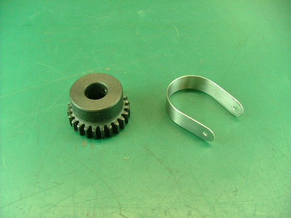
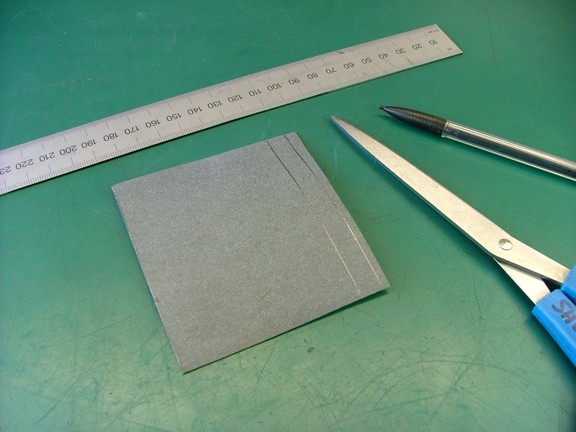
To start off my build I cut out a .330 wide strip of the stainless sheet for use as a brake band.
|
|
|
 |
|
|
I cut the band to a length of 3.125 and then drilled 3/32 holes at either end of the band as seen below. The edges were sanded to remove the burs and then the band was formed to fit over the hub of the magneto gear.
|
|
|
 |
|
|
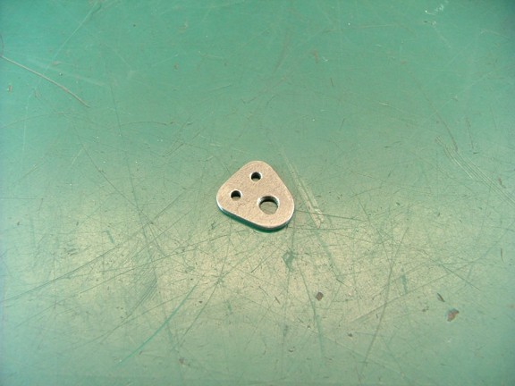
The next step is to make a tensioner bracket out of the mild steel plate. I basically drilled two 3/32 holes and one 9/64 next to each other as seen below.
|
|
|
 |
|
|
Next I cut the bracket out of the plate and then rounded off the corners on my belt sander...
|
|
|
 |
|
|
The next step is to make the brake liner which will be made out of .031 thick gasket material. I cut out a .335 wide strip and then trimmed it to a length of 2.312...
|
|
|
 |
|
|
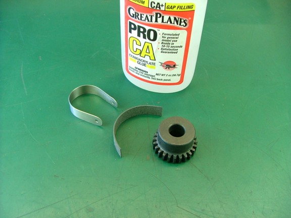
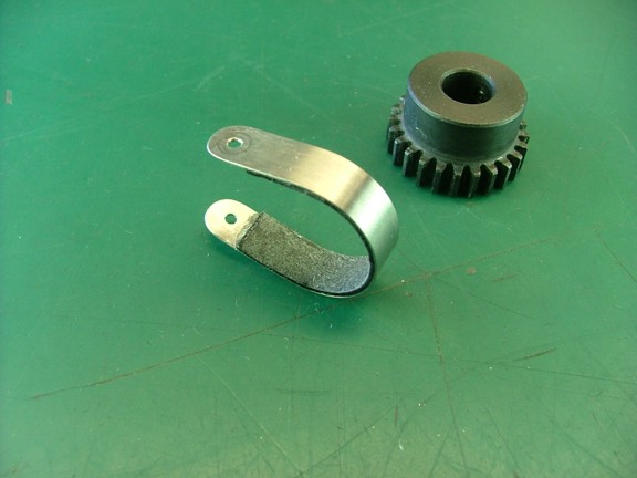
Next I tested the fit of the brake liner in the band. Once I confirmed the correct fit of the band over the liner and hub I was able to glue the liner to the band using some Cyanoacrylate glue.
|
|
|
 |
|
|
I cleaned the stainless band with some acetone before gluing the liner in place. I then carefully glued the liner to the band without getting the CA glue on exposed surface of the liner...
|
|
|
 |
|
|
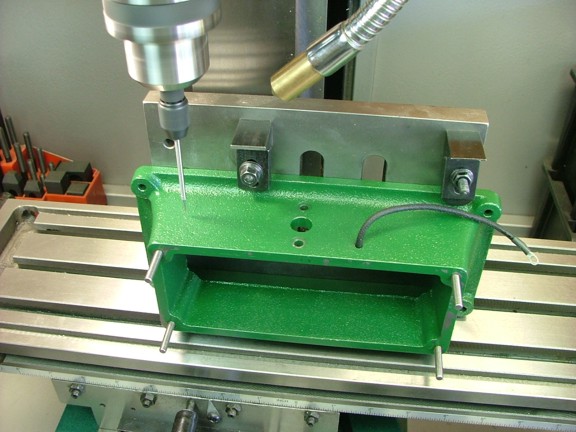
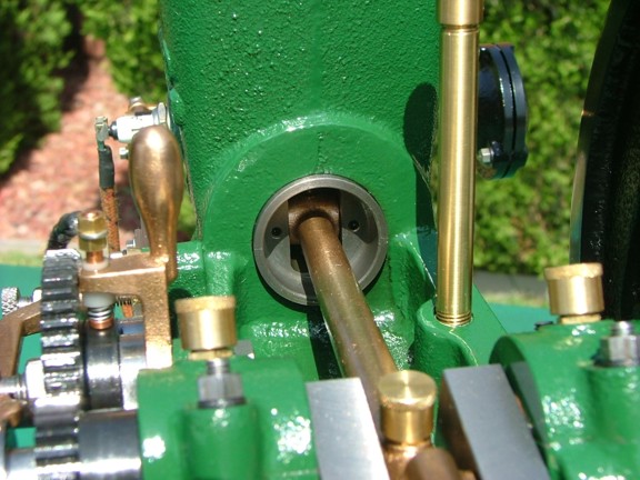
The next step is to modify the engines base to accommodate the tensioner bracket. I centered the spindle over the magneto shaft hole (not shown) and then traversed the table over 2.75 for the bracket screw hole...
|
|
|
 |
|
|
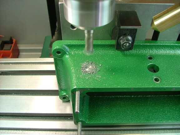
I now used a 5/16 end mill to spot face the base as seen below...
|
|
|
 |
|
|
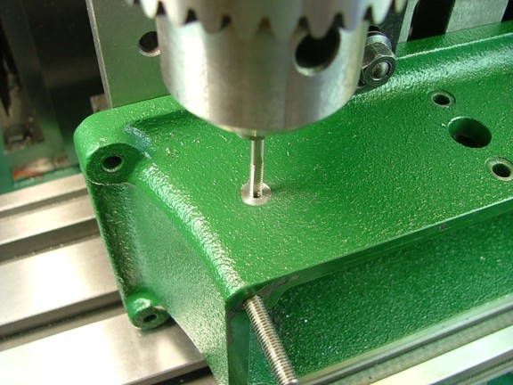
Next I drilled a #36 hole through the side of the base and then chased it with a 6-32 tap.
|
|
|
 |
|
|
The tensioner spring was trimmed down to about 1 long as well as the 6-32 screw which was made into a stud. I also trimmed the aluminum spacer to a length of .315.
|
|
|
 |
|
|
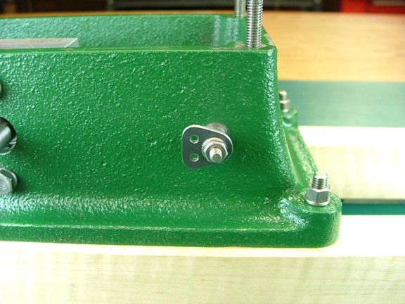
I could now install the tensioner bracket on the engines base using the 6-32 hardware and aluminum spacer as seen below.
|
|
|
 |
|
|
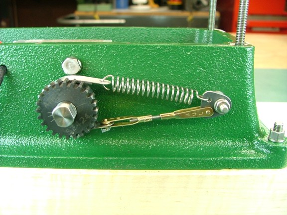
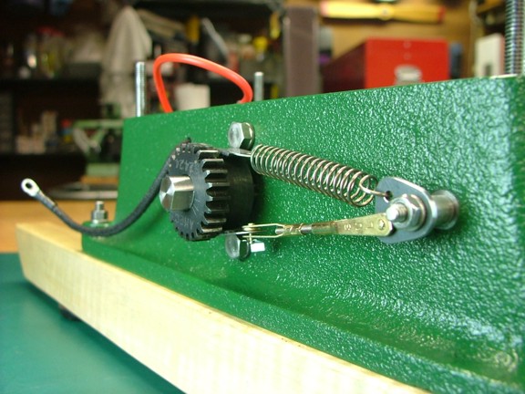
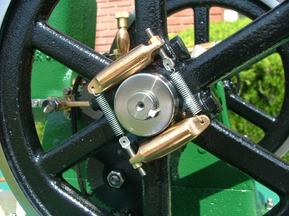
Next I installed the brake band with the clevis linkage on the bottom and tensioner spring at the top. I adjusted the length of the clevis linkage so that the top and bottom sides of the brake band were vertical to each other...
|
|
|
 |
|
|
I could now assemble the engine and test the new friction brake to see if it will quiet down the timing gears. My fingers were crossed :0P
|
|
|
 |
|
|
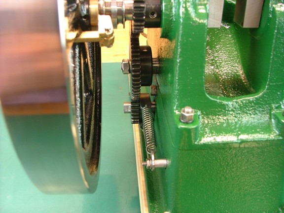
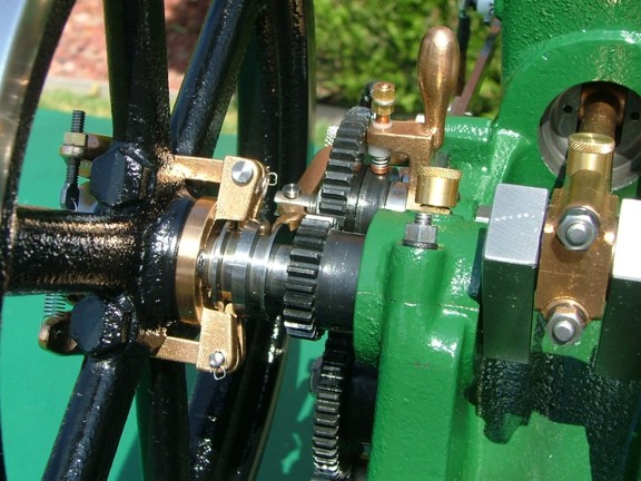
I realigned the timing gears and then reset the magneto to fire at 0° TDC as it was set before. I could tell already that the gears were much more quiet just by turning the flywheels by hand :0)
|
|
|
 |
|
|
I now lubed up the timing gears and prepared for another test run.
|
|
|
 |
|
|
I fired up the engine again except this time I was excited to hear the sweet and subtle sound of the valvetrain ticking away as the engine made a fupp...tic...tic...tic...fupp sound :0) The new friction brake worked flawlessly for such an easy modification...
|
|
|
 |
|
|
I continued to run the engine for about 3 hours and then readjusted the tensioner spring by trimming a little off of it to tighten the brake band (not shown). Once the brake band was broken in on the magneto gear hub the engine sounded like a sewing machine. Not only is the friction brake a success it hardly effects the coasting duration of the flywheels which is a big relief.
I was very concerned that I made a mistake in my timing gear design and now I am sure it was the best setup for this application. Problem solved ;0)
|
|
|
 |
|
|
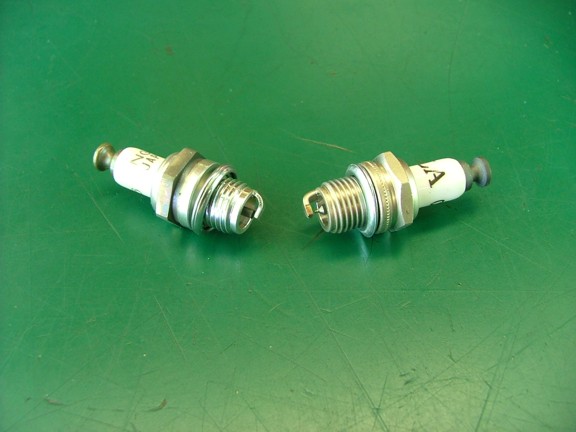
After running the engine for several more hours I discovered a new issue to deal with :0P The CM-6 spark plug (below left) that came with the engine was fouling up with carbon on a regular basis. It seems that the wide electrode has the tendency to accumulate carbon until it bridges the gap and stops the engine :0/ Normally this is not a problem on most gasoline engines as the plug temperature is high enough to burn off the carbon deposits.
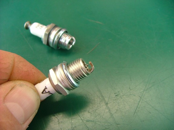
Unfortunately my hit and miss engine does not fire on every four cycles which causes the plug to remain relatively cool without an engine load so carbon build up is a problem. I decided to see if there was an alternative to using the CM-6 plug and found an Iridium CM-6 that has been used on model aircraft engines successfully. This new DLA CM-6 style Iridium plug (below right) has a narrow electrode that will resist fouling as well as outlast the standard CM-6 plug by hundreds of hours of operation.
The DLA Iridium plug can be purchased through SE Model Products for about $6 each
|
|
|
 |
|
|
I set the new plugs gap to .012 and installed it into the engine for a test run.
|
|
|
 |
|
|
I fired up the engine with the new plug and tested it for several hours of run time. The DLA plug collected quite a bit less of the carbon that was fouling out the old plug and only required a occasional cleaning with a soft rag to remove carbon from the electrode. I decided to advance the timing to 3° Before Top Dead Center (BTDC) to increase the operating temperature of the plug and help clear up any residual carbon problems.
After I increased the timing I noted a 15° F increase in the engine's head temperature which leveled out to 170° F without a load (water temp was about 155° F). Between the new plug and advanced timing I am able to get trouble free runs with very little adjustment of the mixer. I can even hand start the engine which is pretty cool ;0)
The red wing engine will now run for four hours on 45¢ of fuel!!! Thats an ounce of fuel per hour without a load!
|
|
|
See a video of the engine running here!!!
|
|
|
 |
|
|
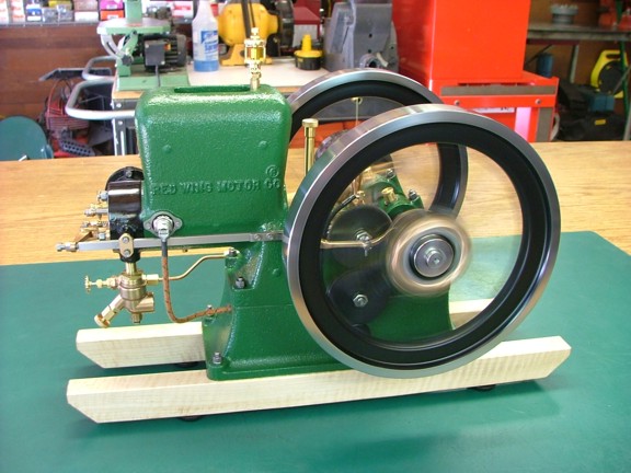
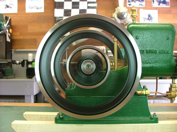
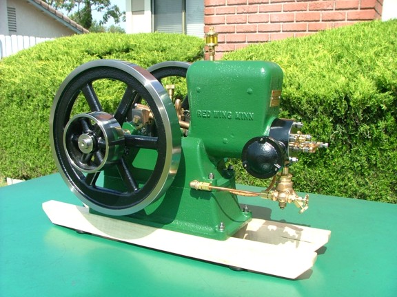
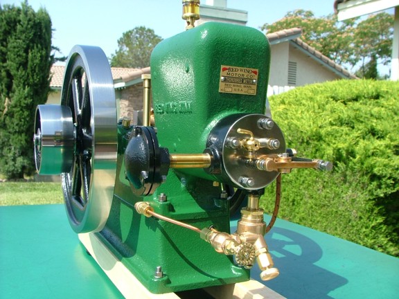
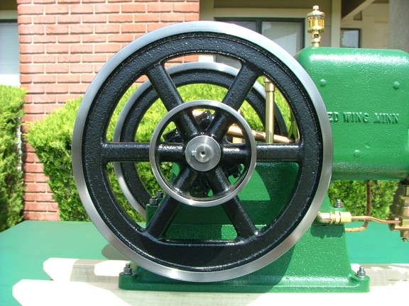
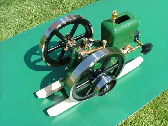
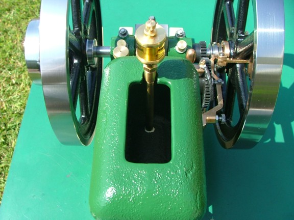
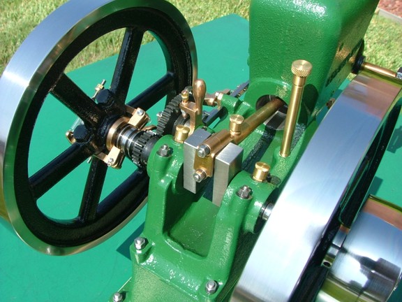
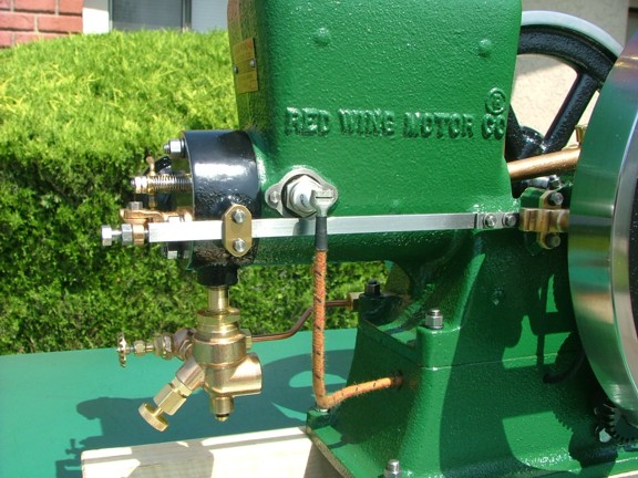
The Red Wing engine is now running beautifully thanks to the new spark plug and advanced timing. The cylinder compression is very good now that the rings are broken in which also helps the engine run really smooth. Currently the engine hits on every eighth revolution at idle (no load) which is a reasonable coast duration for this size engine. I estimate that this engine is producing about 1/6 shaft horsepower at 600 RPM and quite capable of doing real work should I decide to build a machine for the engine to drive.
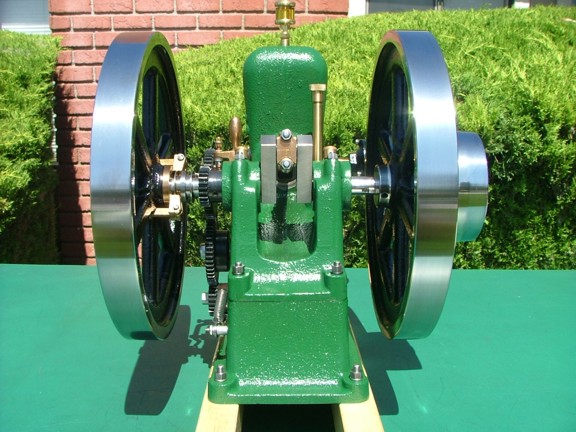
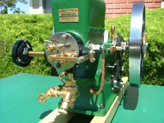
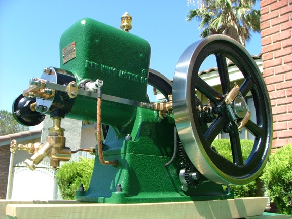
Here are a few pictures of the finished engine:
|
|
|
 |
|
|
 |
|
|
 |
|
|
 |
|
|
 |
|
|
 |
|
|
 |
|
|
 |
|
|
 |
|
|
 |
|
|
 |
|
|
 |
|
|
 |
|
|
This kit took a total of 186 hours over a four month period to complete. That is not including the 75+ hours I spent taking a total of 5,400 photos and then making a 31 page article with 1,358 photos :0P That averages out to over 16 hours of work each week additional to my already busy life :0P I have to admit it was a lot of fun though ;0)
I dont feel that I rushed this kit although I did stay focused throughout the build. I would say that an average builder could finish the basic Red Wing kit in four months if he or she were to spend 8 to 10 hours a week in the shop. However there are some that may not have an extra 8 hours a week to spend on this kit and that is OK. The way to really enjoy a project like this one is to enjoy making every part while learning new methods along the way ;0) There is no need to rush!!!
This is the kind of project that when finished you can share for many years, possibly with your great grand children ;0)
|
|
|
 |
|
|
Overall I could not be more happy with the outcome of this project. Not only do I have a beautiful running engine to enjoy, I have the experience of building it under my belt. I can now tackle the next machining project with more confidence and efficiency. I just need to buy a bigger house to display all of my engines ;0)
|
|
|
 |
|
|
Thanks again for joining me on this adventure, I enjoyed having you guys along for the ride. Your positive e-mail comments have pulled me through my most ambitious build article to date! It is because of faithful readers like you that I choose to publish these articles free of charge, giving back to the internet community and proving that money isnt everything. Just inspiring people to learn and build makes me feel like a million bucks ;0)
Please come back and visit the site again as I am sure I will get into something new before long ;0)
Until then keep learning my friends!!!
Don R. Giandomenico
|
|
|
|
|
|
|