MakerGear M2 Project

<<< Previous Page

Next Page >>>

Page 9

       The next big test was to print a compressor wheel like the one my Friend Andreas printed for me at the beginning of this adventure. For this STL file I used a wheel from Thingiverse that I modified to have a flat bottom so it prints flat on the build platform. I sliced the file in Slic3r and loaded up the G-code into my machine for my next print ;0)

       This print was done with a .30mm layer height instead of .25mm to save some time. Even at this reduced resolution the print took almost 4 hours to complete!!

       The G-code required to print this compressor wheel has almost 298,000 individual lines of code!!! 

       To me this was the most fascinating build I had seen so far. It was hard to leave the machine as I was so intrigued by the slicing software's ability to choose a toolpath to create such a complex shape. Watching it unfold real time was a real treat ;0)

       A couple hours into the build I checked the stepper motor temperatures with a non-contact infrared thermometer (not shown). I noticed that the X and Y motors were running at 49° C which is fairly cool for such a “active” build. The Z axis motor was running at 42° C which is great however the extruder motor was running at 58° C. This temperature may damage the PLA printed motor mount so I kept an eye on it’s condition throughout the build.

       Finally after 3 hours and 55 minutes the compressor wheel was complete!

       I was extremely satisfied with the quality of this print especially on how well the M2 was able to handle the overhang of the compressor blades without using supporting structures. This is a really fine example of what the M2 is capable of.

       At this point I was super excited to print more so I looked for another mod to print for my machine. I found an extended spool holder on Thingiverse that will fit different types of filament spools better than the stock one (below left) so I printed one in PLA (below right).

       The new spool holder bolted right into place. We are now entering an age where parts for things can be downloaded and printed as they are needed.

       Now that I have put some 20+ hours on my machine I felt it was a good idea to lubricate the rails to prevent any unnecessary wear. For this I like to use a product called Super-Lube which is a clear PTFE enriched synthetic lubricant. This stuff has the right viscosity for the M2 and is clear so it doesn’t look messy on the rails.

       Along with the Super-Lube I use lithium grease which works really well with lead screws that have bronze/brass lead nuts. The M2 comes with a small container of lithium grease of which I chose to put into a syringe for easy dispensing.

       First I applied some of the Super-Lube to an epoxy brush.

       Next I applied the grease to both of the linear rods to lubricate the bearing carriages and also keep the rods from rusting. This grease will stay put so it’s the best bet for long term rust prevention (IMHO).

       To lubricate the linear rails I applied a layer of grease into the V-channel on both sides of the rails and then moved the carriage back and forth to lube the bearings inside. An alternate method of lubing the rails is to inject the grease into either of the two opposing metal lubrication ports on the linear carriages (as per the manufacturer’s instruction).

       To lubricate the lead screw I applied some white lithium grease to an epoxy brush and then applied it directly to the lead screw. The lithium grease can be substituted with the Super-Lube if it is unavailable however lithium grease works very well for metal to metal friction so I prefer to use it in this case.

       I applied the grease to the lead screw by “homing” the z-axis while brushing the grease onto the screw. It doesn’t take a whole lot, maybe a aspirin sized dab of the stuff.

       Now that the machine was lubed and cleaned I decided to look into a few more mods. One of which I felt was important was to add a support wire for the build platform as seen below. The wires coming out of the heated build platform are continuously being moved and the weak link is where they attach to the platform. It’s just a matter of time before the wires break and a replacement heater will have to be ordered.
       My fix to this is a simple one. I just added a stainless steel wire support that bolts onto the spider from below which still allows you to remove the build platform from the spider when ever you want.

       The wire harness basically sits into a yoke that supports the wires and prevents the harness from wagging back and fourth when printing. This will prolong the service life of the heated build plate wires and prevent unnecessary damage to the system.

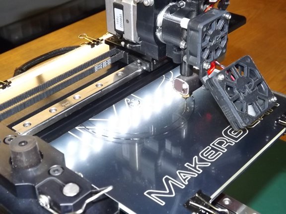
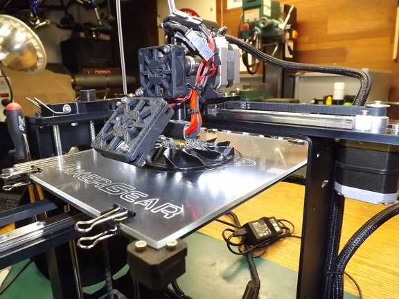
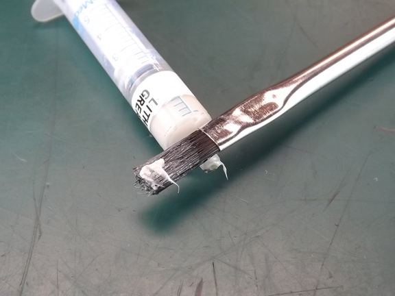
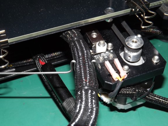
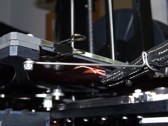
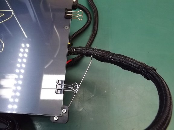
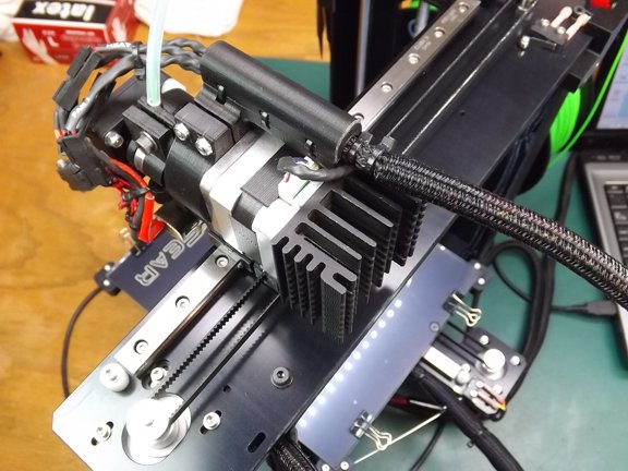
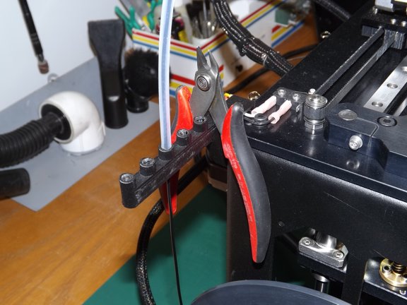
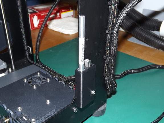
       To secure the wire I replaced one of the original HBP mounting pad screws with a M3 x 20mm spare parts screw and a M3 Nylock nut (seen below). The support wire can be made of any rigid wire like coat hanger wire or in my case, stainless steel welding filler.

       This was an easy mod and it works really well.

       The next mod I wanted to work on was fixing the excessive heat from the extruder motor. Earlier I had measured 58° C (136° F) temperatures from my extruder motor which to me is too hot. Ultimately that heat weakened the PLA printed extruder motor mount and cracks started to appear making the motor clamp loose (not shown). I was forced to print a replacement mount out of ABS material which is more resilient to heat than PLA. Unfortunately that was only a band-aid and a real solution was needed.
       I had seen users adding fans to the back of the extruder motor however I feel that is not needed here and a simple silent heat sink would do the trick. I had dug through my pile of electronics surplus in the garage and found a 50 x 52 mm Aavid “old school” CPU heat sink which fits great on the back of the extruder motor ;0)

       I drilled a couple of holes and milled a pocket (seen above) to clear the cable support bracket of the motor mount. I then found two M3 x 28mm screws that are long enough to bolt the heat sink to the back of the motor. Note: The milled pocket is not necessary as the printed motor mount can be trimmed as an alternate method of clearance.

       Next I removed two opposing screws from the motor and applied some thermal silicone grease to the back plate of the motor as seen below...

       Lastly I installed the heat sink which really looks good ;0)

       The addition of the heat sink dropped the motor temperature to 45° C which is much better than before.

       The next heat issue I wanted to fix was in the power supply. The M2’s power supply has a built in fan that is somewhat enclosed by a plastic outer case which forces the air to recirculate inside of the enclosure. This circulation does very little to pull in cool air and just heats up the whole box. In fact the plastic case gets surprisingly hot which provoked me to find an easy solution to the problem.
       First I drilled a set of alternate holes above the original cooling holes in the case in sort of a zig-zag pattern (seen below). This will improve the air flow by at least 100%. Next I cut out a foam block that is used as a baffle that will force the fan to expel the hot air out of the enclosure’s front holes and pull in cold air from the back holes.

       You can see below how the foam block divides the air space and forces the air to follow a different path.

       After I closed up the enclosure I ran the printer and found that the enclosure hardly gets warm at all now. This will prolong the life of the power supply greatly.

       The next “upgrade” was to buy a set of good wire clippers to cut filament. I picked up these “Hakko CHP-170” cutters for under $5 on Amazon which are the best cutters on the market (IMHO). They are Italian made and really work well for clipping small copper wires and in this case plastic filament.

       These clippers sit nicely on the filament guide I printed earlier so they are always ready for a filament change.

       The next “upgrade” I chose to get was a valve tappet feeler gauge (Lisle 68050) which has angled blades as seen below. The angled blades make it much easier to measure the gap between the extruder nozzle and the build platform during alignment.

       I use the .203mm blade to adjust the height of my build platform.

       I added a piece of stainless wire to the gauge set so it can be hung on the tool holder I printed earlier...

       The next tool I wanted to have on hand was a metric micrometer to measure the thickness of filament. For this I found a Shars 0-25mm metric outside micrometer on eBay for about $15 shipped which works great for what I need.

       The micrometer has a plastic case that fits perfectly into the M2’s frame. I used a piece of Velcro to secure the tool in place and now I will always have a way to measure filament where ever I take the machine.

       The last addition to the machine I added was a X-Acto knife holder that my good friend Rick Silz made for me on FreeCAD. I sent him a drawing and he designed a mesh file for me that printed up this little beauty. It is really handy to have an X-Axto knife while printing and now I will have one ready all the time. If you would like a copy of this STL file to print your own knife holder feel free to E-mail me and I will send you the STL file or G-code if you like.

<<< Previous Page

Next Page >>>

[Home] [What's New At RCDON] [Articles] [Aircraft Projects] [Aircraft Videos] [Aircraft Videos II] [Experimental Projects] [Experimental Projects II] [Nixie Tube Clock Project] [6CI Steam Engine Project] [Vertical Boiler Project] [The Toolroom Tune-Up Project] [The Reverse Tumbler Project] [Red Wing Engine Project] [MakerGear M2 Project] [The LED Studio Light Project] [My Collection] [RC Links] [About Myself] [Contact RCDON]