|
|
 |
|
|
 |
 |
 |
|
Posted on June 12, 2009
Building the GR-7 over the past few years has been a real learning experience. So many facets of the project have shown me valuable fabrication and design skills that I will carry with me “forever”. In this one project I have learned how to TIG weld stainless, machine relatively complex parts out of raw stock, design and build an evaporative combustor system, understand basic concepts of thermodynamics and so much more. I’m pretty sure that nobody will be able to convince me that this project was a waste of time and resources.
Luckily for me my gas turbine education has not ended yet. I still have the daunting task of building the ECU (Electronic Control Unit) for the GR-7. The ECU will control all of the automatic engine functions including a fully automated startup cycle and shutdown as well. The ECU will provide engine monitoring and emergency shutdown capabilities along with automatic safety fail safes designed to prevent operational hazards.
Since the beginning of this project I have had ideas of how I want the ECU to operate but nothing on paper. I knew I wanted the ECU to control the startup and shutdown/cooling procedure automatically. I also wanted there to be a photo optically monitored flame control system (hence the sight glass on the combustor). I had also envisioned some additional automatic features like the combustor drain and the self engaging starter system. With all of these different systems and functions to tie together I have my work cut out for me.
Note: As to avoid a continuous stream of e-mail requests I must add a disclaimer to this phase of the GR-7 project. The purpose of these articles is to share the basic ideas and methods used to create the GR-7 turbojet engine, mostly for entertainment purposes. At no point were these articles designed specifically as “how-to” instructions to build an engine or related parts. Having said this I will still welcome general questions about the build as always. However I must decline to specifics outside of what I have already posted in these articles.
I do not plan on releasing the exact schematics of the GR-7 ECU. At some point in the future I may agree to share the specifics but as for now I wish to save some of my ideas for future development. I thank you for your understanding in the matter...
|
 |
|
|
 |
 |
 |
|
To get started on this phase of the build I decided to start planning how I was going to fit all of the electronics into the ECU enclosure. A hole was drilled into the lower back of the ECU “box” to accommodate an 1-1/4” chase nipple which will allow all of the control wires to enter the box. The location of the chase is important in the beginning as it dictates how the circuit board terminators will be located as well as clearance for future control wiring.
|
 |
 |
|
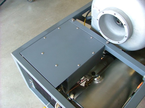
Now that the wire chase is in place I can start figuring out where all of electronics can be placed. One of the existing components of the ECU needs a home close to the wire chase. The Electronic Speed Controls (ESC’s) that drive the starter motors draw a lot of current and need to be close to the starter assembly to keep conductor length at a minimum. I chose to place both ESC’s near the wire chase so the factory connectors can be accessible from outside the ECU box.
To help act as a heat sink I placed an aluminum plate on the inside of the ECU box as seen below. Thermal heat sink paste was used to “link” the plate to the enclosure side.
|
 |
 |
|
I used the existing clamp plate to secure both ESC’s to the box side.
|
 |
 |
|
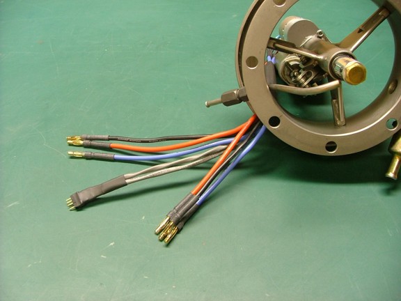
Having the ESC’s in place I was able to install the “bullet” connectors to the starter motor wires. The wires were cut to exact length as to minimize resistance losses. The four pin connector seen below is for the starter solenoid and engage interlock switch.
|
 |
|
|
 |
 |
 |
|
The remaining components of the ECU will need to be fabricated out of loose parts and modified industrial/consumer electronics. This is where things get tricky. When I seriously sat down to figure out how the ECU was going to be built it seemed too complex for me to figure out all at once, and I was right! To build the ECU I needed to break up the project into several subsystems and then tie them together with a final master system. To do this I needed something on paper, a story board if you will.
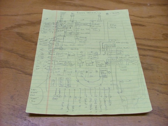
I broke the ECU into several different sections: the fuel delivery control board, the starter shaft control board, the starter motor control board, the ignition coil driver board, the RPM sensor board and the main control relay board. I plotted some of these ideas on paper and made sort of a flow chart describing the desired function of these systems (as seen below). From this scribbled rough chart I hope to build the GR-7’s ECU.
|
 |
|
|
 |
 |
 |
|
Building all of the “daughter” boards was my first goal which would ultimately help me in figuring out the motherboards role in the ECU system. The first board I wanted to build was the Starter Motor Control (SMC) board which has two basic functions: to arm the speed controls upon power-up and slowly ramp up the motors during the startup cycle. For this board I will use a little reverse engineering of a couple of existing products to help me out with the circuitry.
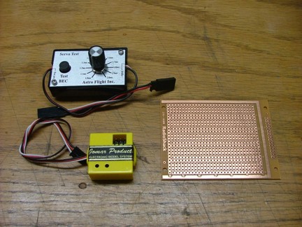
Until now I have been using an Astro Flight servo testing unit to control the Electronic Speed Control (ESC) units (seen below at the top of the picture). This servo tester generates a pulse-width signal that mimics the servo control signal of a remote control radio receiver commonly used in RC airplanes and vehicles. I plan to use this tester unit to automatically control the starter motor speed controls (with a little modification of course).
One challenge I needed to overcome is the fact that the ESC’s I am using (as with most ESC’s made today) require the user to “arm” them before allowing the motor/s to spin. This arming sequence prevents the user from inadvertently throttling up the motors upon initial power-up. Since some of these ESC’s power multi-horsepower motors spinning very sharp propellers I can see where safety was paramount in the design. However in my design I actually want the ESC’s to be automatically armed and ready for startup at power-up.
To normally arm the speed controls in an RC environment one needs to set the remote control throttle stick to 0% and then to 100% and back to 0%. This sequence lets the speed controls know that the user is ready to fly or drive the remote control vehicle. I will need to design a circuit that does this automatically upon power-up of the ECU. Combined in the same circuit I need a way to control the speed of the starter motors as well as the acceleration timing. For this circuit I will be using an EMS Jomar “Servo Go Slow” servo speed reducer (seen below in the yellow enclosure).
The speed reducer will allow me to set the speed at which the starter motors will “ramp” up to full RPM during startup.
|
 |
|
|
 |
 |
 |
|
To get started on the SMC board I needed to break down both devices to their basic form and find my inputs and outputs.
|
 |
 |
|
My plan was to integrate both of these circuits into one circuit board to save space. The first circuit to get cannibalized was the servo tester as seen below.
|
 |
 |
|
I removed most of the unnecessary PCB (Printed Circuit Board) from the servo tester to save space on my new board. I then used some solid wire to solder the servo tester to the SMC board.
|
 |
 |
|
I added a resistor and potentiometer to the circuit to allow for adjustment of the slow speed setting of the startup/shutdown cycle.
|
 |
 |
|
The servo Go Slow unit was next to streamline. I modified the board to allow it to be mounted to my new SMC board with solid hookup wire jumpers as seen below.
|
 |
 |
|
To build the rest of the circuit I sketched out a simple diagram on paper that tied the functions of these boards into the system I need. Following the sketch as a basic guide I start soldering parts in place hoping it will work as it does in my head. More times than not I get lucky and my ideas come together. However sometimes I miss a small detail and the whole circuit needs to be redesigned.
To build the GR-1 and GR-5A’s ECU’s I utilized a very simple architecture of relays and timers. This type of system is very understandable by my mind in where I can “imagine” the operation of the circuit before I build it. This is much like my ability to “build” and engine in my mind long before I ever cut metal. Using a “ladder” style diagram I can build a control circuit and then “test” it’s function in my head using the simple flow-chart like logic on paper.
My day job as an electrician must be why I gravitate toward ladder style diagrams and control circuits. However I rarely get to use them in my niche of the trade which is ironic :0? I guess the real high tech way to build a complex control circuit would be to use a Programable Logic Controller or PLC to control the functions of an engine. However I feel I am learning much more by building a circuit from parts rather than programming a chip. There are advantages both ways but for now I am content with building my “stone age” control circuits.
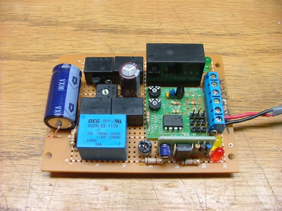
This ECU will be much like the first two utilizing DC relays, capacitive discharge timers and transistors. It is kind of the equivalent of state of the art electronics in the early 40’s with the exception of using transistors rather than vacuum tube assemblies. The biggest drawback to using this architecture is the size of the circuit boards compared to modern compact integrated circuits. This whole ECU could probably fit into a mint tin compared to the shoe box sized unit I am building :0P Nevertheless my ECU will work and function as needed by the end of this phase.
|
 |
|
|
 |
 |
 |
|
The SMC board has taken shape and with a little bench testing receives my seal of approval. You can see the “messy” jumper wires on the back of the board. Using this jumper wire system has an advantage over a printed circuit design being that I can change a connection later on without moving any components on the board. This is especially useful in an R&D environment.
|
 |
 |
|
You can see the original SMC board schematic below which is more like chicken scratches.
|
 |
 |
|
The next daughter board to be built is the Fuel Delivery Control (FDC) board. This board has several functions including the control of the pilot burner, main burner and combustor drain solenoids. The FDC will also monitor the flame with a photocell sensor as well as aid the starting cycle by monitoring the state of the starter motors. Two timers are on this board that help with the photocell flame interlock systems and the starter “spin sensor” which lets the ECU know when it is safe to ignite the pilot burner.
|
 |
 |
|
My model airplane workbench serves well as a electronics workstation. Having a large surface to work on is important with these kind of projects.
|
 |
 |
|
After several hours over a few days I was able to complete the FDC board. I tested the board with the photocell sensor (not shown) as well as the spin sensor circuit and associated timers. You may notice that I incorporate a lot of LED indicator lamps on my circuit boards. These lamps are very helpful in visualizing the proper operation of relays and timers, inputs and outputs. With these indicator lamps you can easily tell what the circuit is doing without a scope or multimeter.
You can probably tell by now that I like my label maker machine as well :0) Labeling important areas of the board are also a very useful diagnostic aid, especially when you have forgotten what you did a few months later.
|
 |
 |
|
This board has a few more jumper wires than the last, it is only going to get more messy as time goes on. I used a little CA glue to bond the wires together and help hold them in place.
|
|