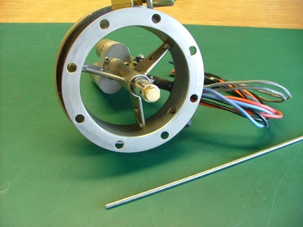
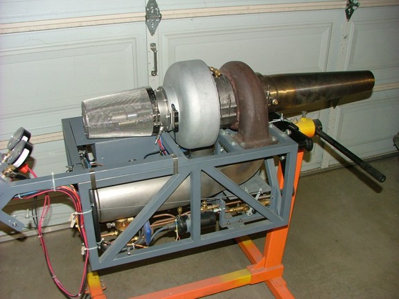
So far the GR-7 project has resumed with little difficulty. The ECU box shaped up nicely and now I was ready to clean up some loose ends before designing the ECU. One of these loose ends was to install the tachometer tube which will eventually hold the fiber optic sensor cables. Long ago I had purchased some 3/16 304 stainless steel tubing for the fiber cables and now I could see if it was going to work.
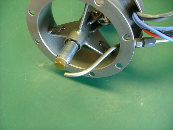
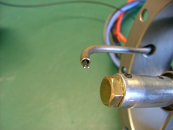
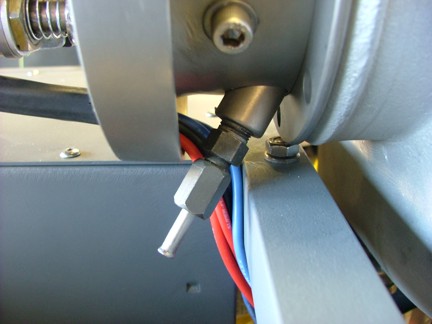
Using my automotive tubing bender I was able to bend the tubing to meet up with the compressor nut on the turbo as seen below. The tubing is supported by a steel compression fitting that has been drilled out to remove the tubing stop in the base.
Once I was satisfied with the fit I used my flanging tool to roll out the edge of the tubing on the exit side to reduce the chance of damaging the fibers as they exit the tube.
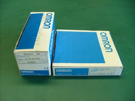
I still am amazed at the deals you can get on eBay if you know what you are looking for. I picked up several hundred dollars worth of Omron sensors for $50 bucks!! I was lucky enough to find several Omron E3X-A11 photo optic sensors and fiber kits which are perfect for turbo based engine tachometer setups. One mans surplus is another mans treasure :0)
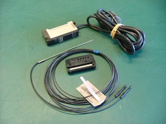
The fiber kit I will be using is a Omron E32-DC200F. These fibers merge at the sensing side into a single stainless steel tube which is really handy for small access locations. In this case I will not be needing the thin tube as I have my own support tube in the bellmouth. Luckily these cables are long enough to cannibalize and use two short pieces from the back end of the fibers.
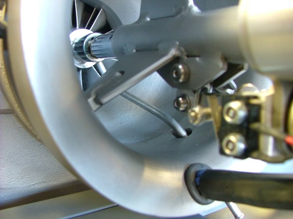
I cut two short pieces from the end of the cables and slid them into the fiber tube for a fit check. You can see the light passing through the fibers in the picture below.
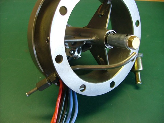
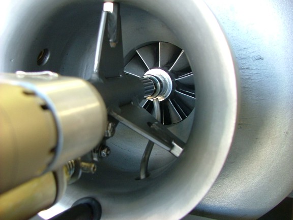
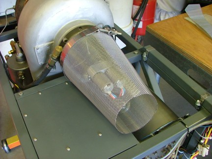
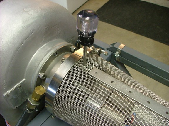
I reattached the bellmouth to the turbo for an alignment check of the fiber tube. Adjusting the tube was easy due to the compression fitting in the bellmouth. I only needed to snug up the compression nut to lock the tubing into place.
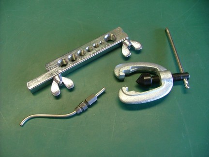
The next step was to fabricate a bracket to hold the Omron E3X-A11 sensor unit in place. I opted to place the sensor near the bellmouth to keep the fibers as short as possible to reduce the chance of damage. The E3X-A11 was designed to mount on a DIN type rail so I made a DIN clone out of 304 SS which worked great. The next step in the sensor install is to epoxy the fibers into the stainless tubing. I chose to postpone this step and wait until I completed the ECU so proper testing of the fiber location could be completed before gluing them in place.
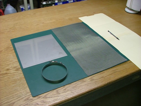
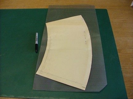
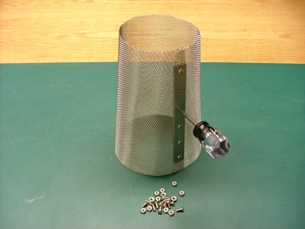
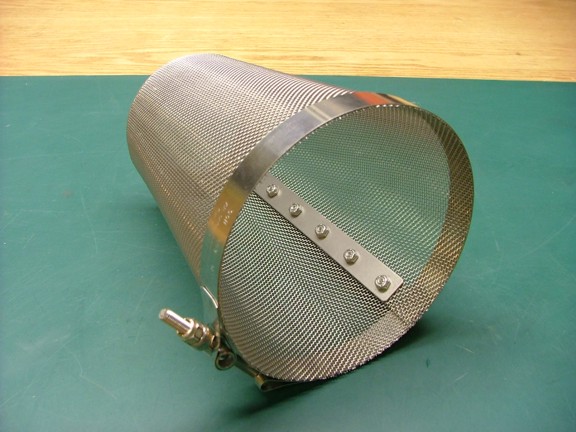
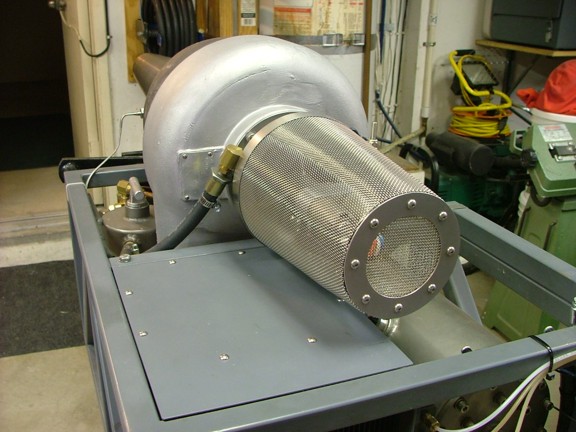
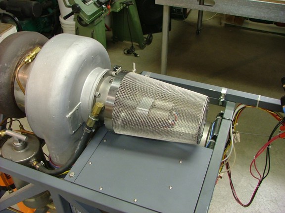
Being as far as I could go with tach sensor I moved on to the FOD (Foreign Object Debris/Damage) screen which will protect the engine from ingesting any harmful debris while running. To make the FOD screen I used some 304 stainless screen woven wire cloth that I had purchased for the build back in 2006. I had researched this type of screen specifically to protect the turbo as well as not to restrict the flow of air to the compressor. What I came up with was a mesh size of 14 x 14 and a wire size of .02. This mesh size will keep out most harmful debris including small rocks or the occasionally misplaced shop rag!! To form the mesh into a useful screen I needed to build a template out of card stock. For me the most useful templates are made of manila folder paper as it is easy to cut and holds its shape pretty good.
I trimmed up some of the card stock to simulate the screen mesh shape as seen below. I used a scrap steel disk to form up the front of the screen template.
Once the template was ready I placed it out on the wire mesh and traced it to the screen with a marker.
Using some sharp tin snips I was able to cut out the basic shape of the FOD screen.
Using a Clampco stainless hose clamp I temporarily secured the screen to the bellmouth for a fit check.
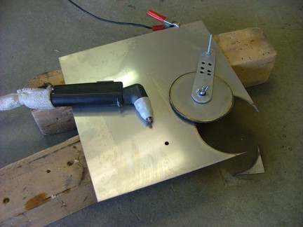
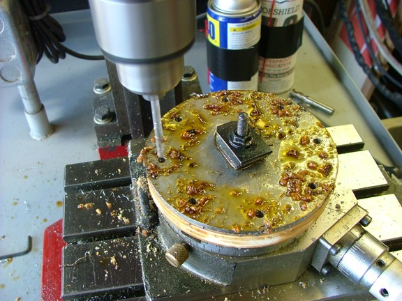
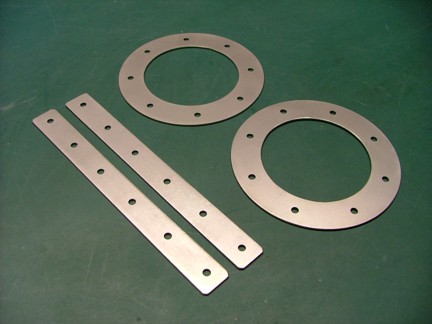
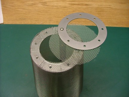
To close up the nose of the FOD screen I needed to make some clamp rings. These rings will sandwich the outer screen with an end piece to complete the envelope. I made the clamp rings out of .058 thick 304 stainless plate and cut them out with my plasma cutter as seen below. Note the use of the circle cutter jig.
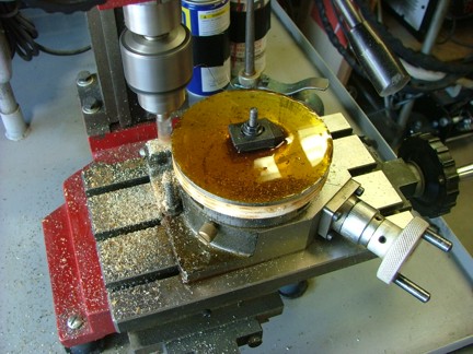
I mounted the disks to my rotary table and rounded them up with an end mill. This is a process that I learned earlier on in this project.
Using the degree wheel on the rotary table I was able to index eight holes through both plates for the mounting hardware. Note the heavy use of cutting oil. Theres one thing I have learned about stainless steel is that you use a good cutting oil and cut as slow as you can or you will be buying a bunch of new bits :0P
To finish up the clamp rings I used a small end mill to chew away through the two plates and complete the rings.
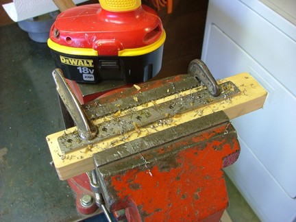
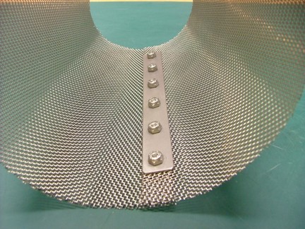
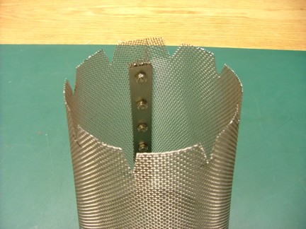
Two clamp strips were also made out of the same material to clamp the seam of the FOD screen together.
Once the clamps were finished and deburred they were sent off to my bead blasting cabinet for a final surface treatment.
And now the tricky part! To get everything perfectly bolted together with the clamps and hardware.
Using a sharp awl I made the first hole through the overlapping screen at the base. I used this hole to install the first 8-32 screw through both clamping strips. Using an awl is the best way to make holes in a screen as it does not cut any of the wires in the mesh.
Once the two end screws were installed into the strip clamps I was able to remove the screen from the bellmouth and finish the rest of the holes. the strip clamps were used as a guide for the remaining holes as seen below.
18-8 stainless screws and nylock nuts were used to secure the clamp strips. The use of the nylock nuts will keep hardware from coming loose and ruining my engine.
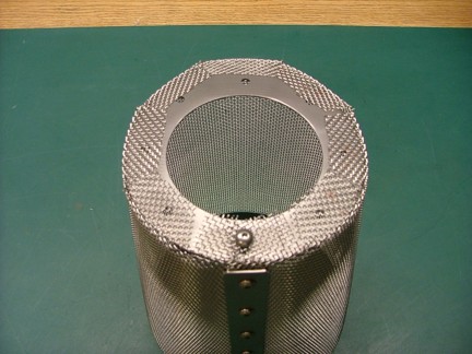
Special cuts were now made at the end of the FOD screen to allow the clamp rings to be installed. It is suggested that you wear gloves when working with this stuff unless of course you enjoy bleeding everywhere :0( It is very sharp when the wires are cut and ends are exposed!
At this point I temporarily installed the end rings to form out the screen where it meets the rings. The screen was formed into place by tapping a small hammer against the side of the clamp rings.
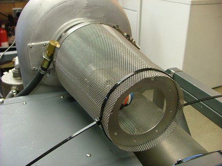
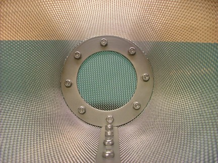
I could now install the end screen and sandwich it to the end of the main screen as seen below.
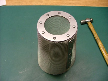
The FOD screen was now finished adding another link into the chain of final completion.
At this point I am pretty excited to finish this long winded project. It has taken a few years and several hundred hours to get this far. Up until this point I have taken 720 photographs and written 300+ paragraphs about the build to boot! I hasnt hit me till now that this project has taken up a considerable chunk of my life. At least an education lasts a lifetime :0)
Be sure to visit again for the continuation of the GR-7 project and join me for the final charge to victory!!!!