 |
 |
 |
 |
 |
|
 |
 |
|
 |
 |
|
 |
 |
 |
 |
 |
|
 |
|
 |
|
|
 |
|
|
|
 |
|
 |
|
|
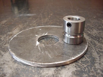
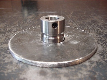
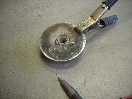
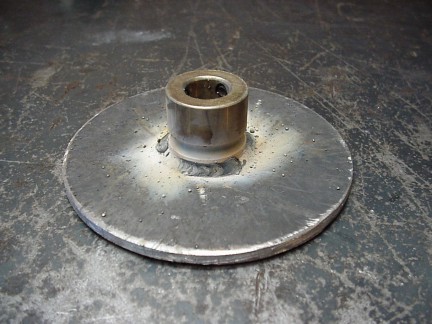
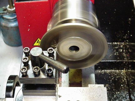
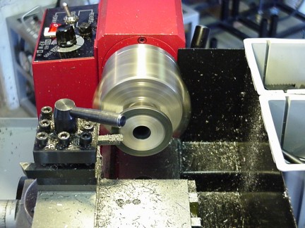
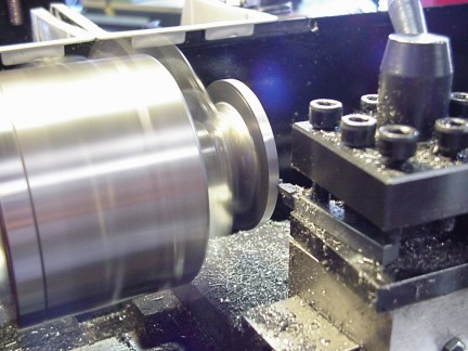
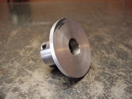
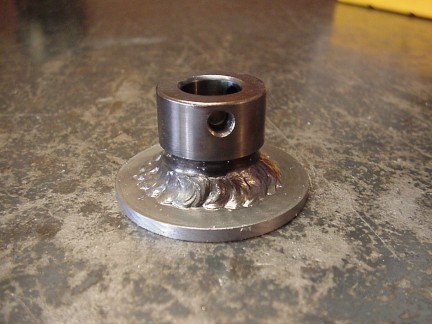
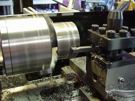
To make sure that the weld will hold, I double beaded it with a lot of temperature. The extra weld had caused the hub to shrink slightly as the great pressure of the cooling metal pulled the bore smaller. To fix this problem, I used a boring bit to slightly widen the bore. The shaft still fit very tight onto the hardened shaft so I used a polishing compound to lightly loosen up the fit. After I ground off the excess weld, I put the hub onto the lathe and cut it to the appropriate diameter to fit into a 2” piece of EMT.
|
|
|
|
 |
|
 |
|
|
 |
|
|
|
 |
|
|
|
 |
|
 |
|
|
|
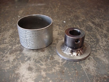
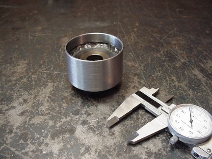
I cut a short piece of 2” EMT for the hub and welded it onto the hub. After the weld was complete, I turned the hub on the lathe to guarantee no runout. I will balance the hub after I weld on the blades, until then I must mount up the turbine housing to the gearbox.
|
|
|
|
 |
|
 |
|
|
|
 |
|
|
|
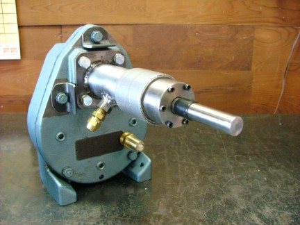
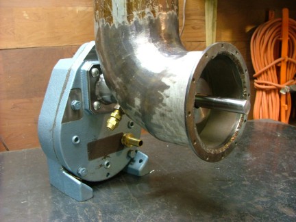
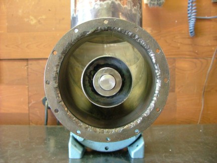
With the hub complete, the alignment of the turbine housing will be easier. I took the newly completed gearbox and wrapped some duct tape around the bearing tube to act as a spacer. The tape will hold the heat shield a uniform distance away from the bearing tube. I temporarily installed the turbine housing onto the bearing tube and then installed the turbine wheel hub.
|
|
|
|
 |
|
 |
|
|
 |
|
 |
|
|
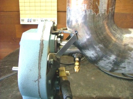
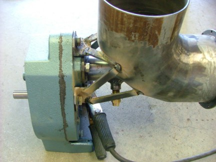
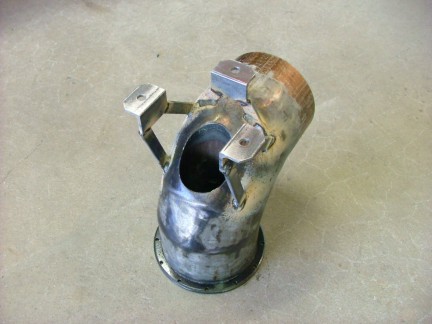
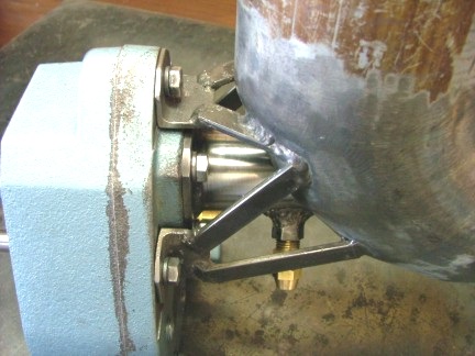
The alignment was very close so I bolted on three pieces of angle iron that I made for the turbine housing bracket. I wanted to make the least amount of heat transfer from the turbine housing/exhaust diverter to the gearbox so I decided to use 1/2” X 3/16” steel bars to make a web style bracket. The steel bars will hopefully keep the majority of heat from transferring to the gearbox. I tack welded the brackets on and checked the alignment of the housing.
The housing seemed to be where I wanted it so I commenced to welding the web into place. Because of some minor heat warping, I had to grind the bracket tabs to get the housing fine tuned.
|
|
|
|
 |
|
|
|
 |
|
|
|
 |
|
|
|
 |
|
|
|
 |
|
|
|
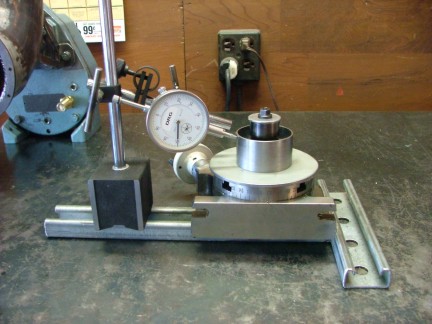
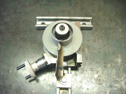
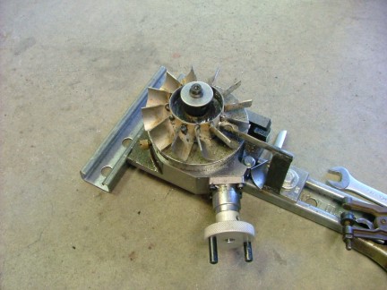
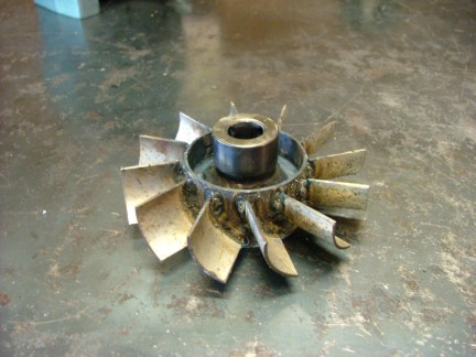
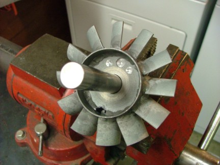
With the successful mounting of the turbine housing I am ready to complete the turbine wheel. I started by making my turbine blades out of the 1-1/4” EMT like I did with the stator section. I made about 20 blades, weighing and measuring them to make a matched set of 12. With the blades completed, I set up my handy turbine jig with the rotary table. I centered the turbine wheel hub with my dial indicator as to assure correct alignment. I had to make a new blade holder as the direction of the blades is the opposite of the stator.
|
|
|
|
 |
|
|
|
 |
|
|
|
 |
|
|
|
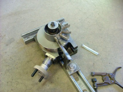
The blade holder has a stop on the top that keeps the blade in the same spot for every weld. Once the weld is completed, the rotary table is advanced to the next 30 deg. position. This would be very difficult to do without this tool and makes the rotary table a wise investment in machining.
|
|
|
|
 |
|
|
|
 |
|
|
|
 |
|
|
|
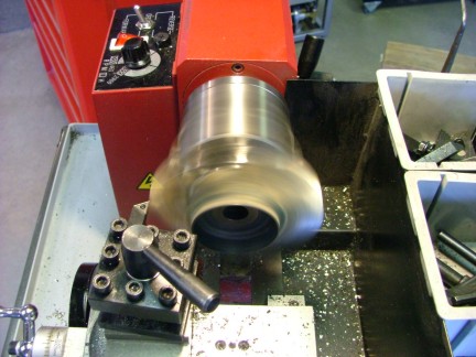
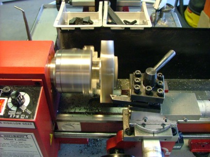
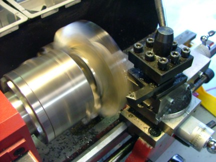
Unlike the stator section, I welded both sides of each blade for strength. The rough turbine wheel is ready to be sized for the turbine housing by turning it on the lathe.
|
|
|
|
 |
|
 |
|
|
 |
|
|
|
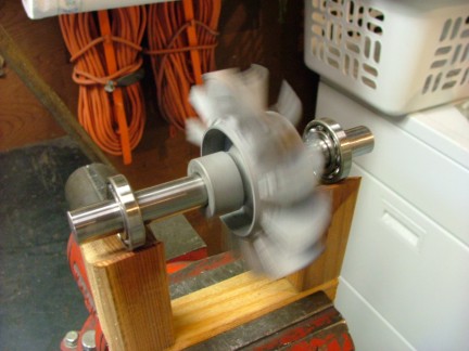
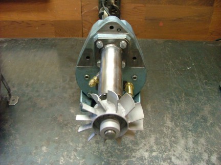
After being cut to size, I sand blasted the wheel and mounted it up on the short piece of shaft leftover from the turbine drive shaft. I made a v-groove stand and used 2 of the bearings I purchased to spin the turbine wheel. After some testing, I drilled some balance holes in the shaft hub which stopped almost all of the vibration when I spun up the wheel with compressed air. It is kind of a rough science but I think it will work.
|
|
|
|
 |
|
|
|
 |
|
|
|
 |
|
|
|
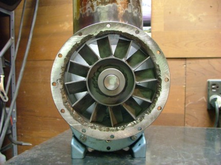
Not really knowing what effects on heat expansion will take on my bracket system or housing, I guessed on what clearances to leave for the turbine wheel. I left 1/16” gap around the wheel as it may expand itself and drag the housing. If I need to cut more off I can but I cant put it back on so better safe than sorry. The turbine wheel looks good and I am eager to get it running!
|
|
|
|
 |
|
|
|
If this turbine wheel works it will make the technology seem much more simple than the aerospace industry does. If this turbine wheel fails, I will research the option of getting one cast out of alloy. Until then , we will have to see if this hunk of scrap pipe will do the job.
Till the next episode....
Don Giandomenico
|
|
|
|
 |
|
 |
|
 |
|