 |
 |
 |
 |
 |
 |
 |
 |
 |
 |
|
 |
|
|
 |
|
 |
|
|
|
Posted on September 12, 2010
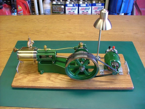
Hello everyone :0) I wanted to share my my little “side project” of adding a generator to the 6CI engine. For several weeks now I have been searching for vintage looking generators and motors on eBay. My hopes were to find a generator or motor that could be converted to a permanent magnet generator. The generator in turn could power a lamp post mounted on the display board with the engine. This way the engine is doing something, not just spinning away.
Unfortunately there aren’t any manufactured generator kits for this size of engine (none that I know of anyway). You pretty much have to make your own in this case. Luckily I was able to find a cheap vintage motor that had a lot of potential as a generator.
|
|
|
 |
|
|
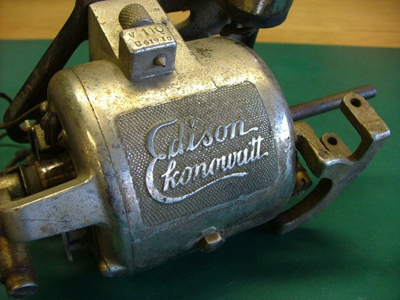
I won an auction for a “Edison Ekonowatt” electric motor on eBay for about $30 shipped to my door. After I received the motor I did some research on it and discovered that it was originally used to power early “cylinder” type phonographs. Even though the motor is quite possibly 90+ years old it is less than collectable because it was used as a “replacement” motor for the original motors supplied with the vintage phonographs.
In fact if a vintage phonograph has this motor in lieu of an original Edison drive motor it will actually depreciate the value of the machine :oP Either way it was good news to me as I could tear this motor apart with a clear conscience that I was not destroying a precious antique ;o)
|
|
|
 |
|
|
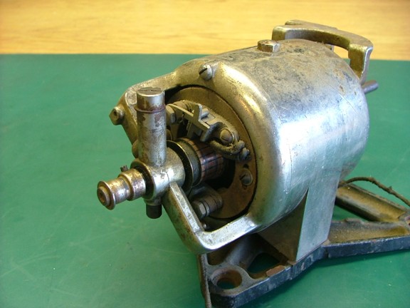
The one cool thing about the Ekonowatt motor is that it has a vintage look to it that will blend nicely into my project. The exposed brushes and peanut shaped vent holes on the front are classic!!!
|
|
|
 |
|
|
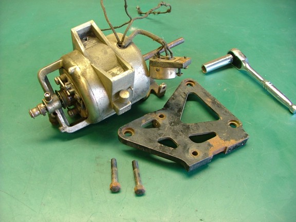
To convert this motor for use as a permanent magnet generator I needed to disassemble it into it’s basic parts....
|
|
|
 |
|
|
I removed the pulley off of the drive end of the motor and used a foam sanding block to remove any rust from the shaft.
|
|
|
 |
|
|
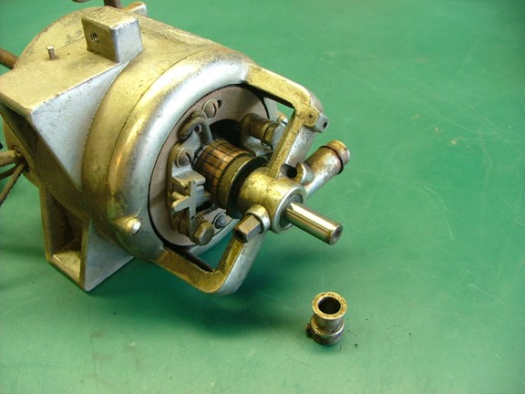
I repeated this process for the opposing side so the armature could be removed from the motor housing.
|
|
|
 |
|
|
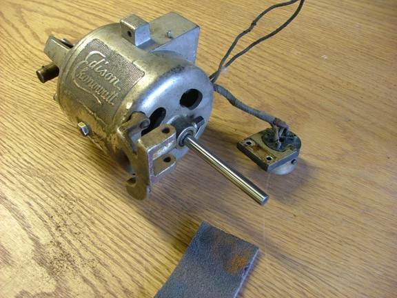
Once the outer cover was removed I was able to get an idea how I was going to modify the motor. The commutators and brushes were in excellent condition which is a ray of hope for my purposes. The bearings were also in great shape considering the age of this motor.
|
|
|
 |
|
|
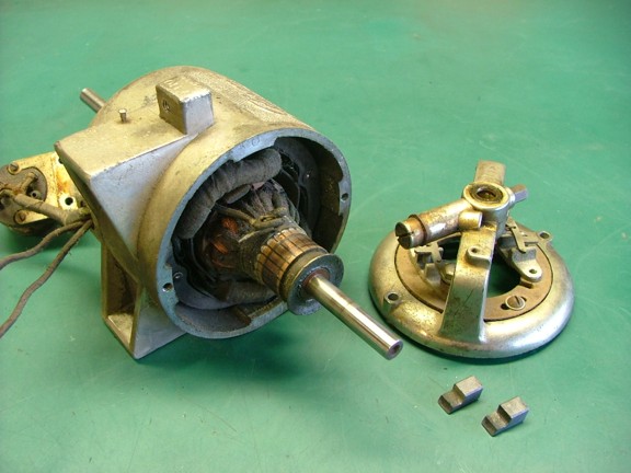
I tested out the resistance of the windings on the armature to see if there was any burned out windings. Luckily all of the cross-measurements were fairly equal indicating that I might have a serviceable armature to work with.
|
|
|
 |
|
|
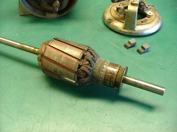
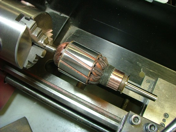
I placed the armature on my lathe and cleaned it up a bit with the foam sanding block. I carefully cleaned the commutators with the sanding block making sure not to disturb the copper windings. I then covered the commutators and shafts with masking tape in preparation for a new coat of polyurethane sealer (not shown). The clear sealant was sprayed onto the armature as it spun on the lathe (to keep the coat even).
|
|
|
 |
|
|
To convert the motor into a permanent magnet generator I would need to remove the “stator” core from the motor housing and replace it with a set of permanent magnets. The permanent magnets would come from a “donor” motor that I already had (below).
|
|
|
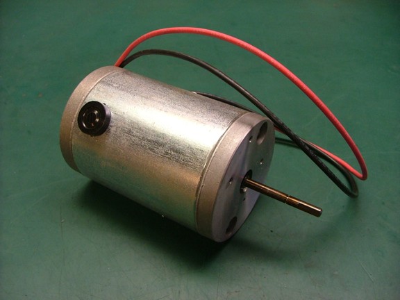 |
|
|
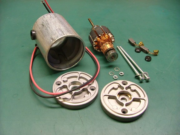
I disassembled the donor motor and harvested the useable parts for other projects as well as the motor casing for this project...
|
|
|
 |
|
|
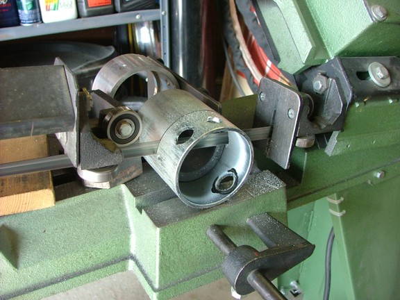
I decided to use the donor motor’s casing to hold the permanent magnets in place. All I had to do was trim down the casing to fit into the old Edison motor housing...
|
|
|
 |
|
|
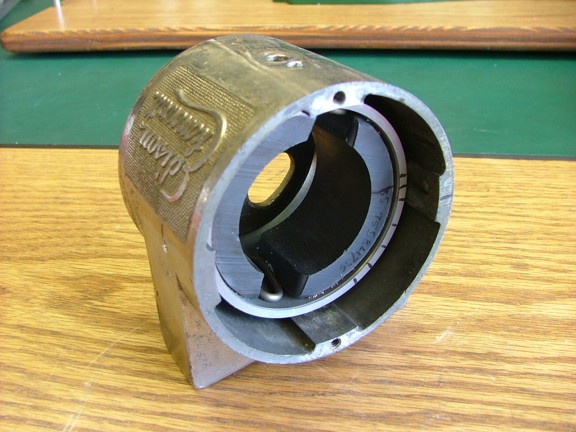
Using a series of 4 set screws (not shown) I was able to secure the new magnets inside the old housing as seen below. The set screws will allow me to later rotate the magnets to advance or retard the field timing, maximizing power output of the generator.
|
|
|
 |
|
|
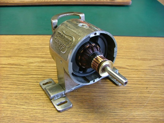
The next step was to build a steel support base for the generator. I used some 1” wide mild steel bar stock to make the “H” shaped base as seen below. You will notice the slots where the mounting screws go. This will allow me to adjust the belt tension of the generator later on.
At this point I temporarily assembled the generator and tested it to see what voltage it could produce. At around 2,200 RPM it produced 130 volts DC!!! However the voltage dropped dramatically under load so it was decided to run the generator at about 1,700 RPM which produces 24 volts @ 2 amps full load.
|
|
|
 |
|
|
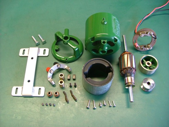
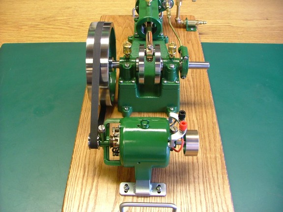
I had to build a few extra parts to make the generator work as planned. One of which was a new pulley that was made out of cold rolled steel (seen lower right). The pulley, when used with the flywheel of the engine will produce about a 6.8 : 1 pulley ratio which will spin the generator at 1,700 RPM at full engine speed.
Another “add on” was the load balancing flywheel (seen middle right). This bronze flywheel was intended to help equalize the uneven speed of the steam engine by adding to the rotating mass of the armature. I used a small steam engine flywheel casting for this part and machined it to fit the shaft of the generator.
Once I was happy with the final setup I started preparing the generator for paint. I sand blasted some of the parts including the motor housing which had chrome flaking off of it. It cleaned up nicely as did the base and terminal post bracket. I degreased everything with automotive brake cleaner prior to painting and then sprayed on several coats of green automotive acrylic enamel (the same paint used to paint the engine).
|
|
|
 |
|
|
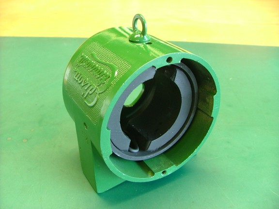
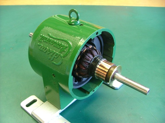
Once the paint was cured I could start the final assembly. Notice the eye-hook on the top of the generator. This was made from a split washer and a 5/16” screw. I soldered the washer into the groove of the screw to create the scale-looking hook.
|
|
|
 |
|
|
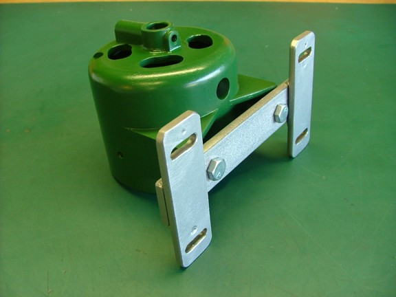
Next was to bolt on the base....
|
|
|
 |
|
|
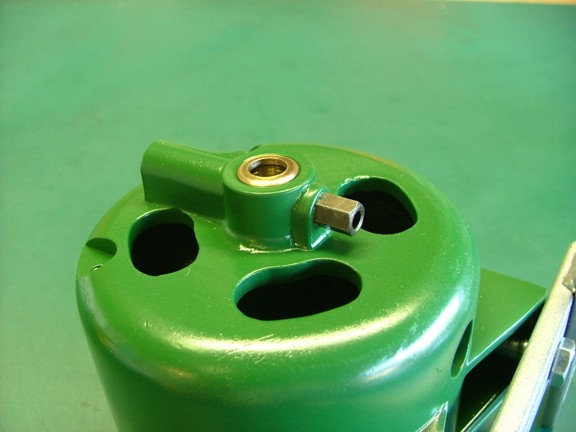
And now the bushings......
|
|
|
 |
|
|
 |
|
|
 |
|
|
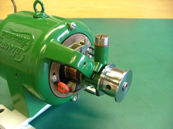
The newly completed 1” diameter pulley was installed onto the shaft. Notice the bevel on the face of the pulley. This will help the belt track in the center of the pulley guides....
|
|
|
 |
|
|
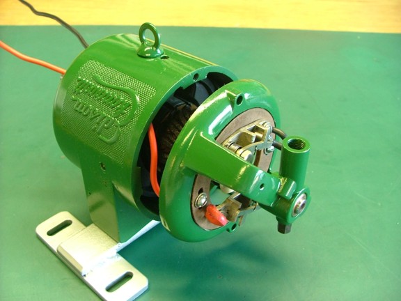
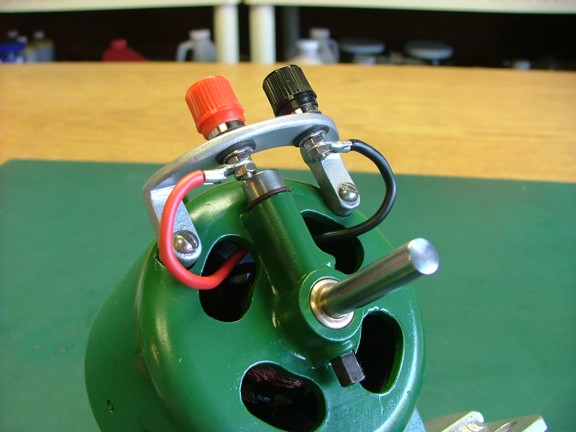
The terminal post bracket was installed to the generator and wired up to the brushes. The wire was run inside the generator for a neat appearance.
|
|
|
 |
|
|
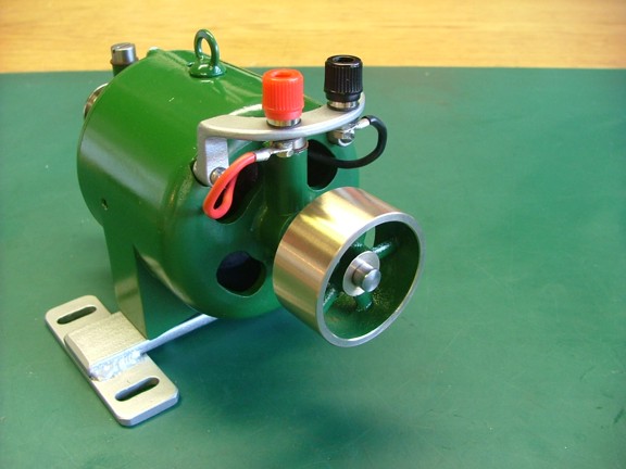
The load balancing flywheel was the last to install.
|
|
|
 |
|
|
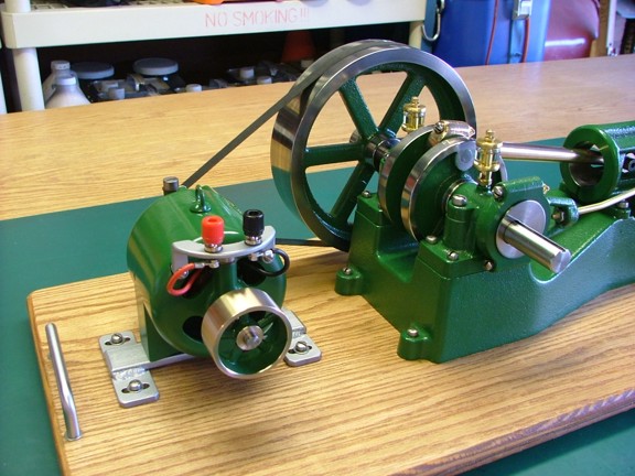
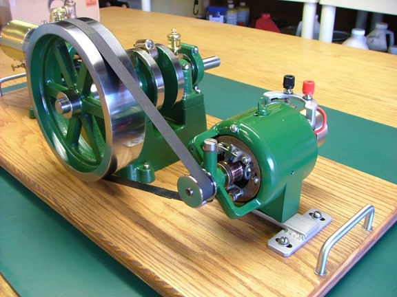
I bolted down the generator to the display board using some stainless 10-24 screws and blind nuts. A 1/2” flat belt was then made to fit the pulleys. I purchased this reinforced rubber belting on eBay from a model engineer supply. The belting was cut to length and glued together with “super glue”.
|
|
|
 |
|
|
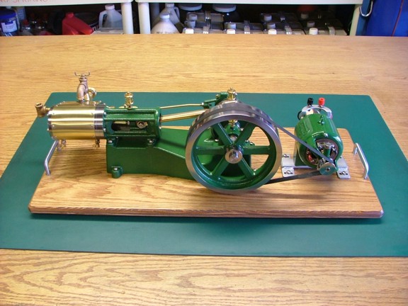
I couldn’t wait to fire up the engine so I broke out the air hose and gave the genny a spin.
|
|
|
 |
|
|
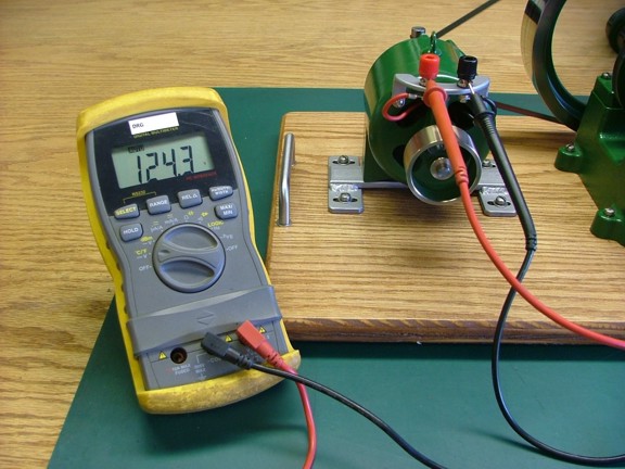
The belting tracked quite nicely on the pulleys as the generator whirred away. I tested the output voltage which was as high as 125 volts!!!
|
|
|
 |
|
|
At this point I needed a 24 volt load to test the output of the generator under load.
|
|
|
 |
|
|
 |
|
|
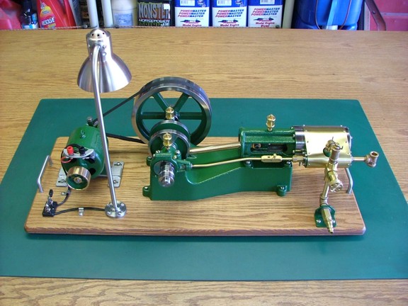
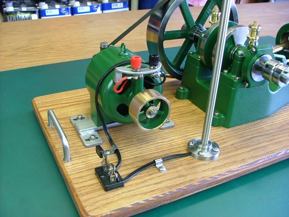
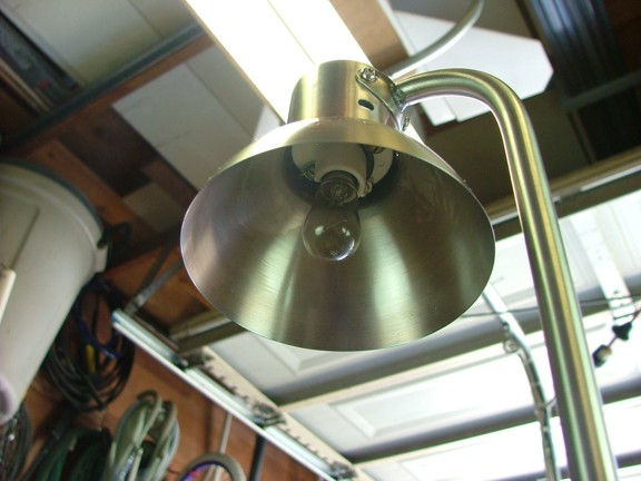
To help demonstrate the generator’s power output I decided to build a lamp post. I used several elements to build the post including a machined lamp post base, 3/8” stainless steel tubing for the post, modified desk lamp head and a candelabra “keyless” style lamp base for the lamp. I installed a knife switch to control the flow of current to the lamp and a 24 volt 10 watt lamp into the lamp post.
|
|
|
 |
|
|
 |
|
|
 |
|
|
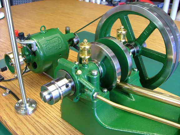
I fired the engine back up and flipped the knife switch. The engine started to make more of a “chugging” sound similar to a steam locomotive under load. I was making power!!! (well actually I was converting one form of energy to another :0).....
|
|
|
See the engine running here!!!
|
|
|
 |
|
|
I ran the engine long enough to heat the generator up to about 95° F!
|
|
|
 |
|
|
The generator project was a big success!! I am very pleased with the function and vintage look of the converted motor. Thank you Mr. Edison for building a fine motor :0)
|
|
|
 |
|
|
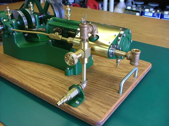
The needle valve I chose to use for the throttle is working perfectly as well. I am super happy with the controllability and consistency of the engine’s speed, even when the load is suddenly removed....
|
|
|
 |
|
|
I can’t seem to talk enough about how much I enjoyed this kit. I can completely see how this could be an addicting hobby, building and collecting engines :o) Now I will need to start thinking about a boiler to run my new engine. An experimenters work is never done ;o)
|
|
|
 |
|
|
I want to thank everyone for checking out my project. I had a lot of fun building this one :0) I would also like to welcome you to check out my vertical boiler project where I build an all copper boiler for this engine!!!. Until the next time, dream big and build big my friends!!!
Take care,
Don R. Giandomenico
|
|
|
 |
|
 |
|