|
|
|
|
|
 |
 |
|
Page 1
|
|
 |
 |
|
The Top Flite B-25J Mitchell Project
By Don Giandomenico March 20, 2008
|
|
|
 |
 |
|
Several years ago I saw a B-25 fly at the Chino Air Show in California. The sound and beauty of this warbird impressed me so deeply I decided right then and there that I would one day build a remote control model of one. It wasn’t long before I found a kit with high ambition of building one that summer. I ended up getting a Wing Manufacturing B-25 kit that unfortunately sat on my workbench for four years. Needless to say I did not get very far on the project.
|
|
 |
The truth of the matter was that time was not on my side. The more I wanted to get into the kit the less time I had for a several hundred hour project. I learned from building my EC-47N (Top Flite DC-3 Kit) that it sometimes takes many months to complete a kit and honestly I really would much rather fly than build at this point in my life. Now this statement was not meant to take anything away from kit building in fact it is a testament to the devotion and hard work a kit builder puts into his creation. I cherish my EC-47N and never regret the time I spent on it but I would probably wait for my retirement days before I build another one :oP
Around June of 2007 I had heard about a couple of ARF (Almost Ready to Fly) kits that were coming out in the 80” size range I was looking for. I had already been accustomed to the quality of the Top Flite brand so I gravitated to the kit they offered. I ordered the Top Flite B-25J Mitchell ARF in late August and eagerly awaited the backorder from Tower Hobbies. In the meantime I sold my Wing Manufacturing kit to a good “home” where it would get the attention it deserved. I had already purchased most of the on board equipment for the Wing kit and was hoping to use it in the TF B-25 so I held on to most of it.
I got my B-25 around the middle of November and this time I meant business. I cleared out my garage and built a 8’ X 4’ workbench specifically for the build. I moved most of my building supplies into the garage and set up camp for a quick and speedy build.
|
 |
|
|
 |
 |
 |
|
During the few months I awaited the kit I had time to hash trough my existing stockpile of parts. To round out my parts list I ended up buying the Robart retract setup for the B-25 along with some additional servos I would be needing but for the build.
|
 |
 |
|
I had originally purchased two Satio FA-90TS twin cylinder engines for the Wing kit and I was determined to fit them into the TF kit. I was convinced that the sound of the twins running would be impressive and worth the effort of installing them. I am a big fan of Saito engines and these are real gems!!!
|
 |
 |
|
All I needed at this point was some time to devote to the build so I cleared a few weekends and informed everyone I would be “working in the garage”.
|
 |
 |
|
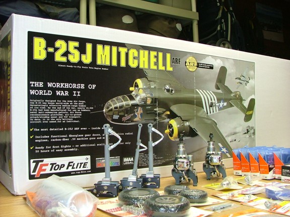
The B-25 kit came in a large box, 66” X 20” X 12” to be exact. It took up most of my new workbench!!! It was packed very well using a series of individual boxes for the more delicate parts. I spent a good amount of time inspecting the parts for damage and double checked the parts list for missing items if any.
|
 |
 |
|
The fuselage of the B-25 takes up a good part of the shipping box at 64”+ long. It is a beautiful piece of work and hardly weighs anything.
|
 |
 |
|
After rummaging through the parts I found everything listed including a few additional decals and a hardware upgrade. The only damaged part I could find was a slightly damaged leading edge on one of the inboard wing panels from where it rested against the wing tube package. Other than that I was ready to build!!!
|
 |
 |
|
I spent some time reading through the instruction manual to get an idea of what was ahead of me. The manual seemed to be complete but had some room for detail improvement. There were some steps that were not followed up with an illustrations to support them. I would be willing to bet that there will be an updated version of the manual if this ARF survives the test of time.
|
 |
 |
|
One of the first steps the manual mentions is to re-iron the covering on the model which is a good idea overall. The covering was wrinkled in a few places on the wings and fuse so I used my covering iron with a “hot sock” to lay the Monokote back down. I made sure to remove all of the masking tape that the factory applied to the parts to hold them together prior to ironing. I also removed all of the tape’s residue with acetone and a cotton cloth.
|
 |
 |
|
I used a Coverite pocket thermometer to help set the iron to about 340 deg. Fahr. which helped keep the covering from bubbling from too much heat.
|
 |
 |
|
The ironing process takes a while, expect to spend at least an hour or so to carefully seal the covering to the wood. You will more than likely see minor wrinkling come back over time but at least you will have the big stuff taken care of now. When ironing out the big wrinkles be sure not to press hard or else you may crease the covering making it permanently visible. It is important to take your time and iron slowly. If you start having trouble ironing out small bubbles it helps to use the side edge of the iron to carefully squeegee them down. If all else fails you can use a sewing needle to poke small holes in trouble areas.
To help the time pass ironing I thought of how much work it was for those factory workers to painstakingly cut and apply this covering and how very little I had to do to finish it ;0)
|
 |
 |
|
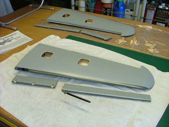
Notice the bath towels I used to protect the pieces as they lay on the bench. The soft balsa under the covering is easily scarred especially on the wing panels so care must be taken to keep them in good shape. A doubled up bath towel works great and also keeps the covering from being scuffed.
|
 |
 |
|
This next step is one of my personal building habits that I usually do to models I “care” about. I like to seal the edges or seams of the covering with thin Cyanoacrylate glue (CA glue) so the dirt and oil cannot loosen the edges and lift the covering. This is especially helpful on glow fuel models where the tail gets drenched with oil from the engines. I used to do this process with a regular “Krazy Glue” applicator and run the glue tube along the leading edge of seams of my wings. I now have a better way of doing it which I am happy to share with you.
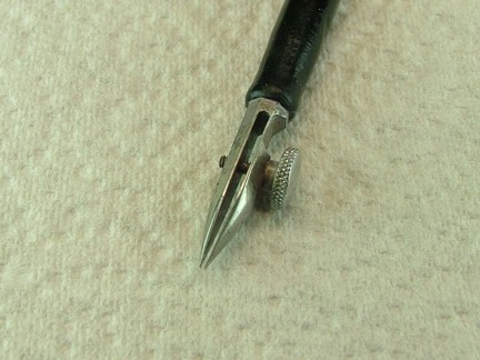
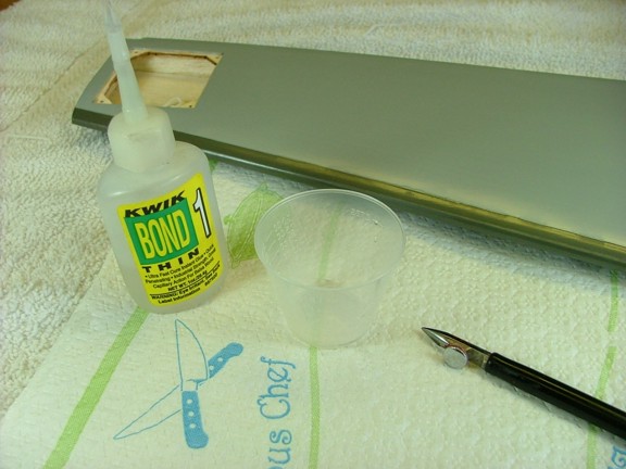
I found an old Vemco drafting “Ruling Pen” that was used to make ink lines with a straight edge. It has an adjustable gap that works to widen or narrow the ink line. In my case I use it to apply CA glue to the important seams of my covering that permanently seals them. I just adjust the gap on the pen and dip it in “medium” or “thin” CA glue. I then “ride” the pen alongside the covering edges and it leaves a very thin line of CA to seal the edges. These ruling pens can still be found on the internet using the search words “Ruling Pen”.
|
 |
|
|
 |
 |
|
|
 |
 |
 |
|
I periodically clean the ruling pen in a small cup of acetone to remove dried glue (very important) or the pen will not work correctly.
|
 |
 |
|
I spend some time preparing the edges that will most likely start to peel when the glow fuel starts to eat at them. The horizontal stabilizer, rudder(s) and control surfaces take the most abuse. I like to seal most of the tail and the wings leading edges if possible. It is a step I am glad I do every time as there is very little you can do to fix oil soaked covering on wood later on. Once I am done with the glue application I let the pieces dry for several hours and use a tack cloth with isopropyl alcohol to wipe any “haze” off the seams. A light coat of “after run” oil works as well just be sure to wipe most of it off after application.
|
 |
|
|
 |
 |
 |
|
The best part about using CA to seal the edges of Monokote covering is that if you make a mistake you can safely clean or remove it with acetone. It is a good idea to practice on less noticeable areas first to get the best “bead” of glue at the Monokote seam. Try starting with “medium” thickness glue and see how it lays down on the seam. If the pen clogs easily try thinning out the glue with “thin” CA. This will allow the glue to flow easily but even faster than the medium CA. It is also a good idea to leave the work piece so that it is level so the glue will not run easily causing drips.
The idea is to get the least amount of CA to just “wet” the edge not fill it. If you get too much glue in one spot you can either quickly clean it with acetone on a paper towel or use a clean paper towel edge to “wick” the excess glue from the seam without distubing the glue line too much. It takes practice but once you master it your covering jobs will outlast the model :0)
|
 |
|
|
 |
 |
 |
|
The next step was to hinge the wings using the supplied hinge points. I applied a small amount of hobby oil to the hinges before installation to keep the epoxy from locking them up.
|
 |
 |
|
I am fairly new to using these types of hinges and I found them quite easy to manage. The key is to make sure you have the right clearance for deflection while the epoxy is still soft or else your surfaces may bind when cured.
|
 |
 |
|
I was now in good shape to work on the nacelles so I prepared my hardware packs by separating the metal from the plastic and nylon. This way it is easier to find the stuff you need.
|
 |
 |
|
The nacelles have a integral structure that bolts to the inboard wing panels with nylon bolts. There are a set of nylon pegs that help align the nacelles to the wing panels. These pegs must be glued into the nacelle structures at the right height or else the structures will not seat correctly. The manual suggested gluing them equally at 3/4” inch but I found that it would not work very well. I chose to carefully measure the depth of the peg holes and glue the pegs in accordingly with 30 min epoxy.
|
 |
 |
|
The inboard pegs I glued in at 12 mm and the outboard pegs were at 17 mm respectively. You will notice that the former on the outboard side is taller to compensate for the dihedral of the inboard wing panels, this is the side that gets the longer peg.
|
 |
 |
|
I used the supplied 1/4-20 nylon screws to hold the nacelle structures to the wings for the next phase of construction. Be sure not to try to mount the wrong nacelle piece to the wrong wing or you will damage the wing sheeting. Each nacelle is marked left and right. If you have trouble getting the screws to start in their holes you can sand the end of the threads into a cone shape to help get them threaded into the blind nuts.
|
|