 |
 |
 |
|
 |
|
 |
|
 |
 |
|
 |
|
|
 |
|
 |
|
 |
|
|
|
Posted on January 3, 2010
Hello again friends! Only a few remaining details keep me from running the GRV-2 on the lakebed again. One of these details is the heat shield for the rear tire of the bike. Since the initial testing of the afterburner I have learned that massive amounts of infrared heat radiation is emitted from the burner duct. So much so that it burned part of the paint off the fender and started to melt the rear tire!!!
It is no surprise that the burner duct emits so much IR heat as it processes about 5.6 million BTUs (British Thermal Units) per hour of fuel through it!!! That is enough BTUs to heat a 112,000 square foot building :0P To help shield the tire and fender from this radiation I will have to build a IR reflector shield. This shield will hopefully reflect the IR heat away from the rear of the bike and save my tire.
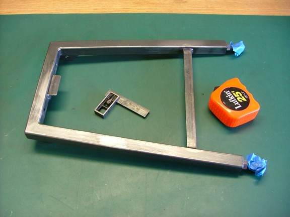
To get started I removed the burner duct support frame and added a set of shield supports as seen below.
|
|
|
 |
|
|
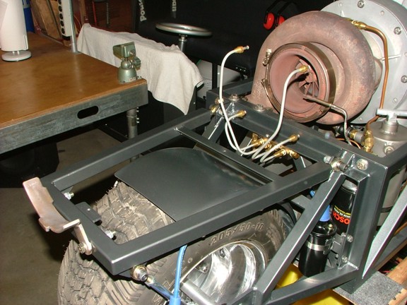
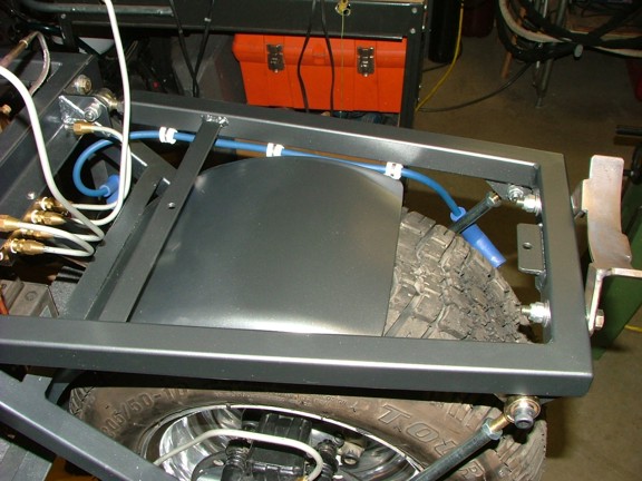
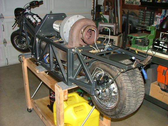
I repaired the paint on the rear fender before installing the modified support frame back onto the bike.
|
|
|
 |
|
|
 |
|
|
 |
|
|
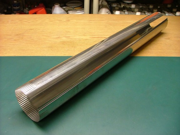
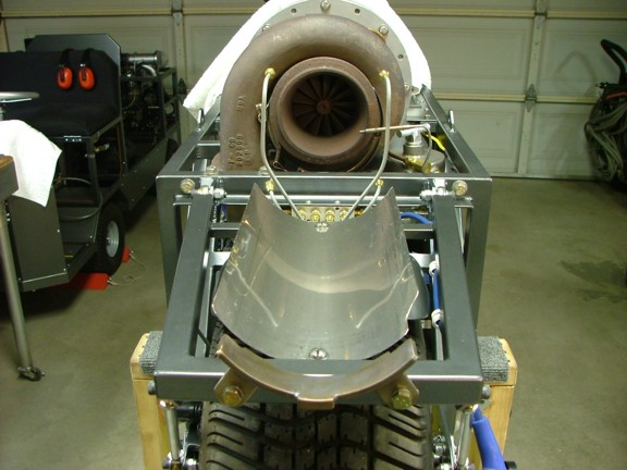
To build the heat shield I employed some polished 26 gauge 304 stainless steel ducting. The reflective quality of this ducting should reflect the infrared radiation quite nicely.
|
|
|
 |
|
|
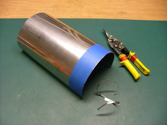
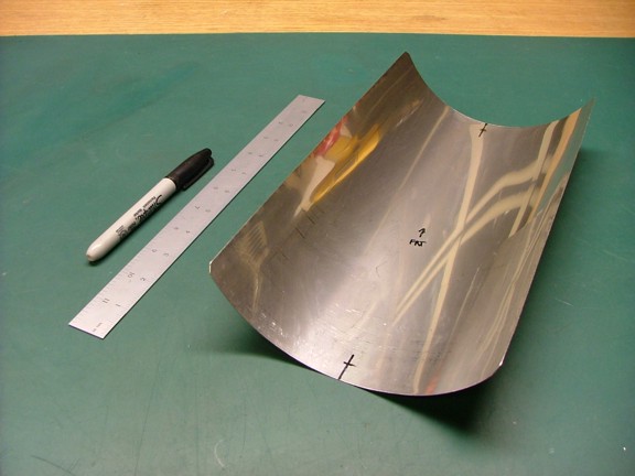
Using a pair of tin snips I cut out a half moon shaped reflector. Using gloves when working with this stuff is always suggested.
|
|
|
 |
|
|
 |
|
|
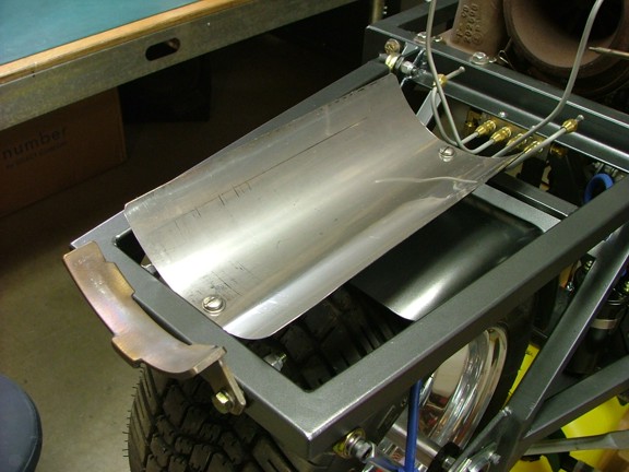
To attach the new shield to the support frame I used a set of stainless 1/4”-20 screws and cadmium plated steel expanding hex locknuts.
|
|
|
 |
|
|
 |
|
|
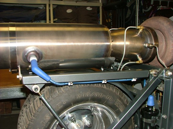
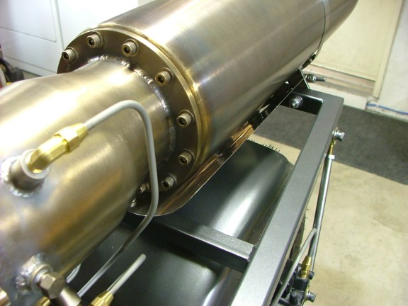
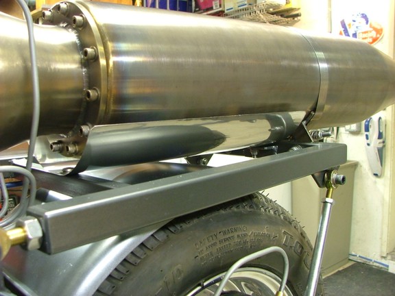
I replaced the burner duct on the bike and adjusted the shield to sit about a 1/2” from the burner duct walls. This will allow enough cooling air to flow between the two and prevent any meltdowns (I hope :0).
|
|
|
 |
|
|
 |
|
|
With the IR heat shield in place I could now focus on the Afterburner Control Module or ACM.
|
|
|
 |
|
|
Controlling the afterburner has always been one of my main concerns for this project. Safely controlling the burn cycles at the appropriate times is of the most importance considering the amount of fuel being used. Just manually dumping fuel into the burner won’t suffice for the GRV-2. This is why I spent some time to develop a controller circuit to prevent any accidental fuel discharges that may cause serious injury or fire later on.
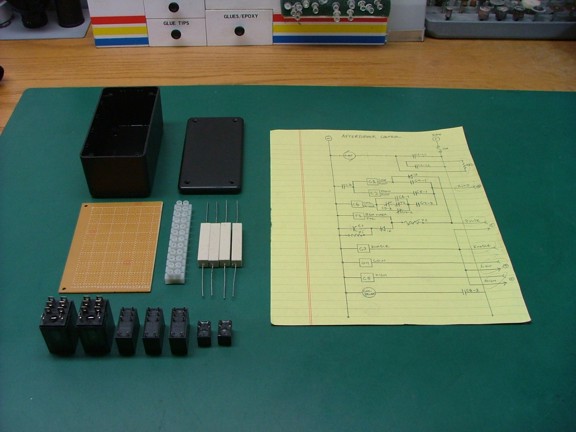
To begin this phase of the build I drafted a “logic storyboard” that describes the functions of the Afterburner Control Module. Much like the ECU of the GR-7 I plotted out the functions that the ACU must perform while in operation. Once the storyboard was complete I started to draft out the ladder diagram for the ACU circuit. This diagram will provide me the “instructions” on how to build the ACU from loose parts.
|
|
|
 |
|
|
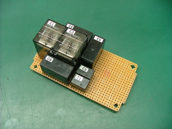
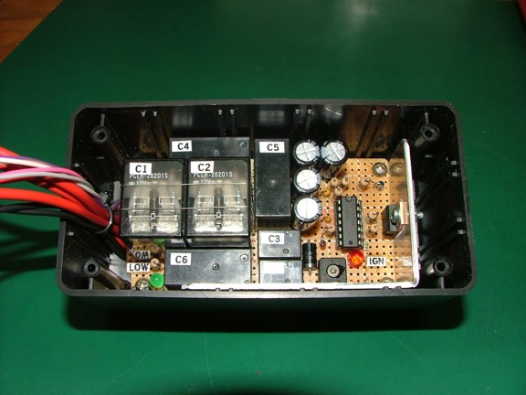
I began to build the ACU by mounting the required control relays to the circuit board. The ladder diagram is very useful at this point as it tells me exactly how many relays and what type to install on the board. As of this point I have two high current fuel pump control relays, one ignition control relay, one ignition timer circuit relay, one “enable” circuit relay and two low/high burn rate relays.
|
|
|
 |
|
|
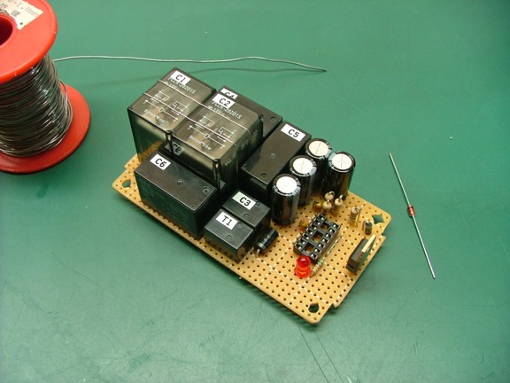
The next step was to add the coil driver circuit to the board. This circuit will drive the automotive coil much like the points and condenser that I was using earlier in the project. This driver is based on the circuit found on Bowden’s Hobby Circuits website (thanks again Bill!!!).
|
|
|
 |
|
|
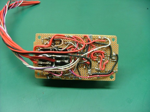
Once all of the components were in place I used my ladder diagram as a road map to finish the connections on the back of the board with jumper wires.
|
|
|
 |
|
|
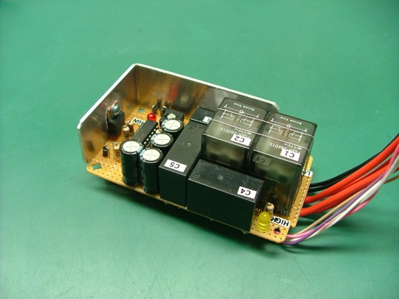
Before mounting the board into the ACM enclosure I added a heat sink to the MOSFET N channel transistor. This is needed as the duty cycle of the driver is high as it will always run while the burner is active.
|
|
|
 |
|
|
The basic operation of the ACM will consist of two operating modes: manual and automatic. In the manual mode the ACM will allow the user to actuate the fuel pump at any engine speed considering the engine is running and the “arm” switch is enabled. This mode will allow the user to pulse the burner manually or just make smoke clouds with the fuel vapor. However the ACM will not allow the ignition circuit to fire unless the engine is running over 10 PSI combustor pressure or 43,000 RPM (minimum ignition engine speed). The ACM will also not allow the burner to ignite unless the engine is running below 20 PSI (61,000 RPM) to prevent high pressure combustion from damaging the engine.
Manual mode will also allow the user to run the engine to full speed without ignition to create enormous smoke clouds :0) This is only possible if the user presses the manual mode button before the engine reaches the minimum ignition speed of 43,000 RPM. If pressed after the 43K mark the burner will ignite and continue to burn through the throttle cycles above 43K. Basically the manual mode if for the “show” aspect of the burner.
The automatic mode will allow the user to operate the burner solely with the throttle control. Once the engine is running and the arm/auto switches are enabled the burner will automatically ignite at the minimum ignition engine speed. The fuel pump will run at about 50% power at the “low” speed setting, producing about 25 PSI fuel pressure (about 20 PSI through the nozzles). This will get the burner running without “popping” due to excessive fuel being dumped into the burner. Once the engine reaches the “high” 20 PSI mark it will go to the full fuel pressure of 50 PSI (about 40 PSI through the nozzles).
As a safety measure the burner will not ignite without the “enable” signal from the GR-7’s ECU. This signal insures that the engine is running and not in emergency shutdown mode. In the event of an emergency the user can still shut down all fuel flow and ignition thorough any one of the three EM buttons on the bike.
|
|
|
 |
|
|
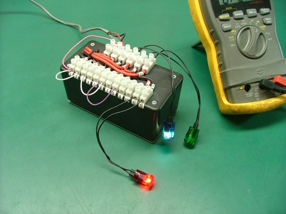
And now for the testing phase of the build. Once the ACM was complete it was necessary to function test the circuit to see if my idea on paper really would work. I hooked up a power supply to the ACM and used jumper wires to simulate the control inputs to the boards. I also used 12 volt lamps to enunciate the control outputs from the board to verify proper operation.
|
|
|
 |
|
|
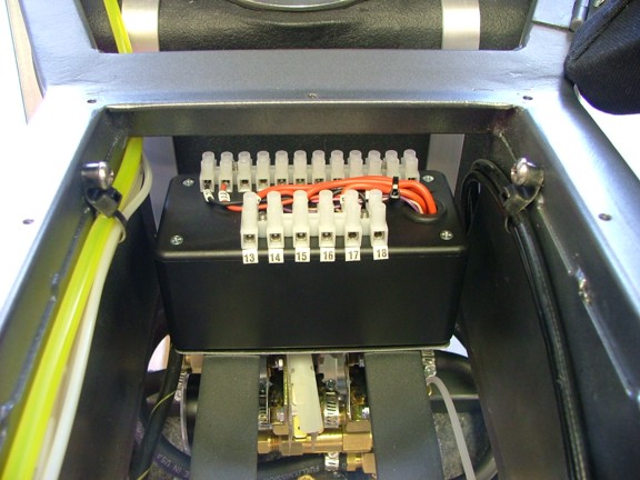
After running the ACM through several scenarios of logic I was reassured that the module will work as intended. It was now time to mount it into the GRV-2!!!
|
|
|
 |
|
|
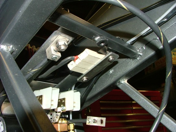
After mounting the ACM into the bike I needed to build the resistor bank (RB-1) which will help reduce the fuel pumps speed at the low burn rate. This bank is comprised of four 1 ohm x 10 watt wire wound resistors in series parallel. The 1 ohm x 40 watt resistor bank will be connected in series with the fuel pump via the low rate control relay in the ACM.
To help dissipate the heat generated by the resistors I decided to mount the bank against the bike frame metal which will act like a heat sink (seen below). You will notice that the rectangular resistors are taped together with fiberglass tape which should handle the heat generated by the bank.
|
|
|
 |
|
|
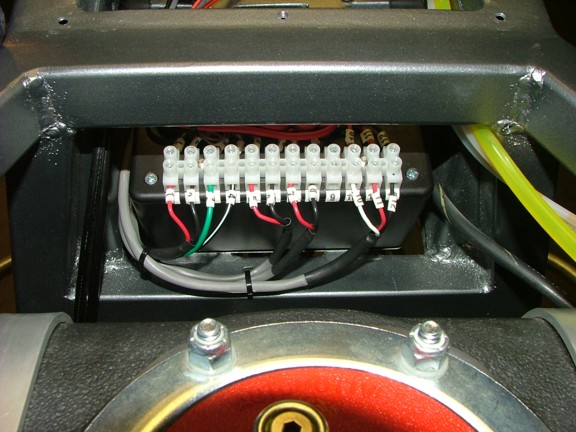
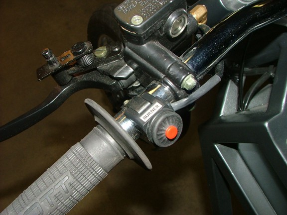
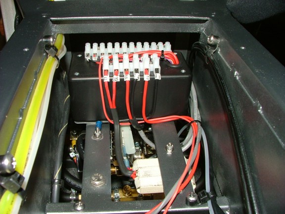
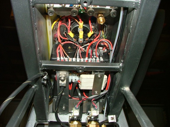
I wired up the resistor bank, pressure switches, fuel pump, remote manual switch and enable circuit to the ACM.
|
|
|
 |
|
|
 |
|
|
|
 |
|
|
Once all of the wiring was in place I installed the control panel back into the bike (with no room to spare ;0)
|
|
|
 |
|
|
I am now in the position to test the ACM at the “test facility” which should hopefully happen within the next few weeks. I am super excited to see how well the two stage fuel delivery system will work :0)
Please join me again for the next chapter in the GRV-2 project!!!
Don R. Giandomenico
|
|
|
 |
|
 |
|
 |
|