 |
 |
 |
|
 |
|
 |
|
 |
 |
|
 |
|
|
|
 |
|
 |
|
 |
|
|
|
Posted on October 14, 2009
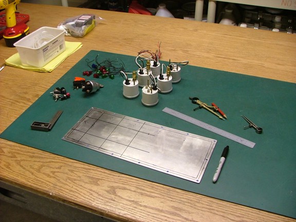
Howdy again folks! I am making serious progress on the Turbochopper these days with only a few details left to sort out before the engine can be run. One of these details is mounting all of the panel gauges, switches and indicator lights. Fortunately I already have the stainless steel gauge plate ready for drilling. All I have to do is lay out the holes and go to work.
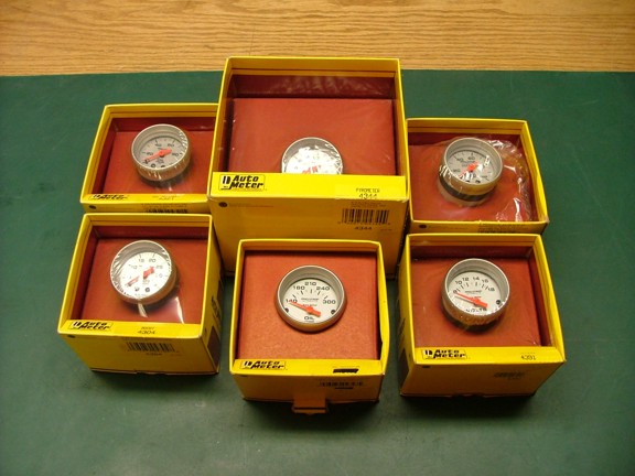
The first task is to mount the Auto Meter gauges that I acquired back when I started the project in June of 2005. I am a big fan of the Auto Meter “Ultra-Lite” 2 1/16” gauges as they are really lightweight and are clearly readable at a glance. However I must admit that this setup cost me a small fortune but the end product will be worth it ;0)
|
|
|
 |
|
|
For this build I will be using a boost pressure gauge (combustor pressure), oil pressure gauge, fuel pressure gauge, pyrometer (TOT), oil temp gauge and voltage meter. For the most part I should have all of the bases covered with these gauges.
|
|
|
 |
|
|
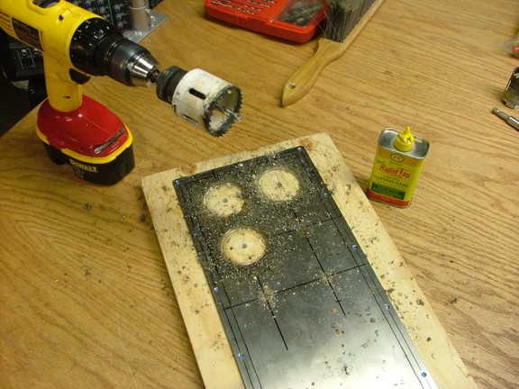
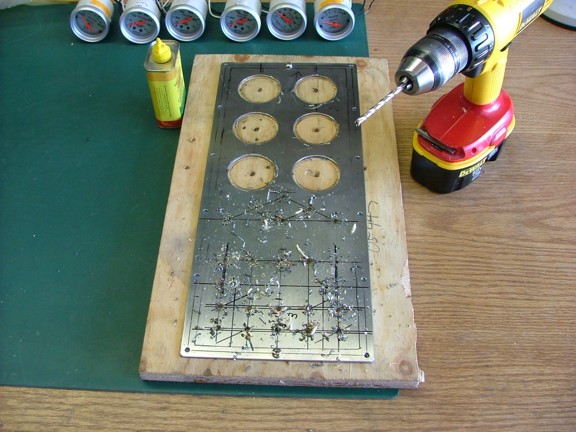
To get started with the gauge install I layed out the gauge positions on the stainless plate. I then carefully used a hole saw and cutting oil to drill out the gauge holes as seen below. Note that I am drilling from the back side of the plate as to not damage the “finished” front surface of the gauge panel. Blue tape was applied to the panel face as to help protect it as well.
|
|
|
 |
|
|
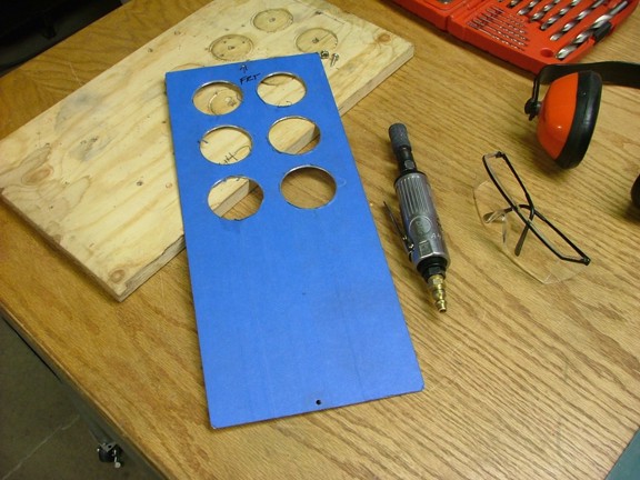
Since the hole saw I was using was a 1/16” too small for the gauges I will need to widen them a bit with the die grinder. After a few minutes of careful grinding I was able to achieve a snug fit for the gauges.
|
|
|
 |
|
|
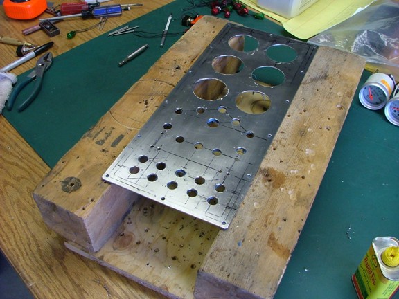
The next step is to drill out the operational switch and indicator light holes in the gauge panel. I spent some time figuring out possible configurations and settled on a “happy medium” configuration for the devices to be mounted. Once the back side was marked I proceeded to drill the pilot holes. I then widened the holes with a step drill to match the switch or lamp used.
|
|
|
 |
|
|
Getting the holes drilled in the right place and not destroying the finished front side was a real challenge!!!
|
|
|
 |
|
|
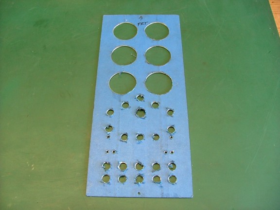
At this point I have deburred all of the holes in the plate and checked that all of the devices will fit in the holes.
|
|
|
 |
|
|
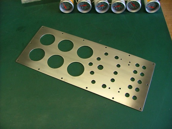
And now the moment of truth!!! Did I destroy the front side of the plate with my machining activities??? Well, I removed the blue painter’s tape to reveal a pristine brushed 304 stainless steel gauge plate. I love it when a plan comes together :0)))
|
|
|
 |
|
|
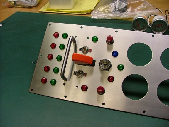
I decided to mount all of the indicator lights and switches to the gauge panel first. I carefully tightened up the switch mounting nuts and applied cyanoacrylate glue (Super Glue) to the nuts to keep everything in place.
|
|
|
 |
|
|
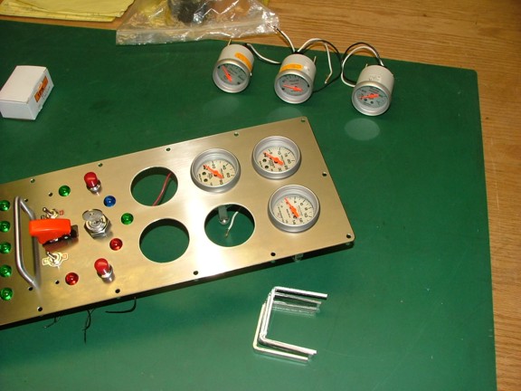
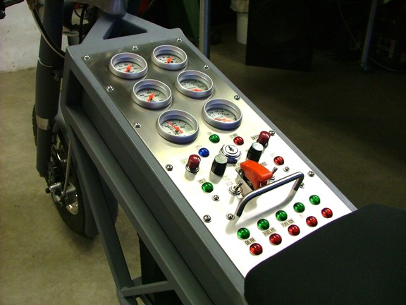
I added the gauges to the panel to complete the control panel. There was no hassle in mounting the Auto Meter gauges as they come with easy to use panel clamps that secure from behind the gauge.
|
|
|
 |
|
|
 |
|
|
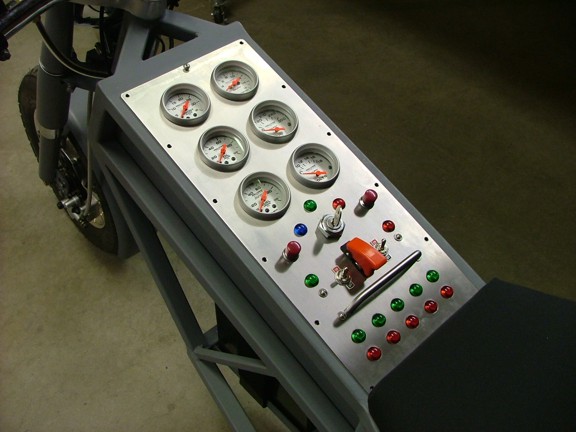
The gauges look really sharp at this point. Now the hard part comes into play, I’ve got to make all of this stuff work!!!
|
|
|
 |
|
|
All of the Auto Meter gauges simply connect to the engine with either pressure tubing or electrical wiring directly. All of these connections are already accounted for on the engine. However some of the indicator lights and switches will require a Control Interface Module (CIM) to connect to the engine’s ECU. This is actually by design and was implemented to reduce the number of conductors used in engine telemetry and control.
In this case the CIM will be controlling several functions including the autostart initiation control, indicator light “flip-flop” control, future afterburner enable control and a special tip-over sensor. The tip sensor will be used to shut down the engine should the bike be in any other orientation than “wheels down”.
|
|
|
 |
|
|
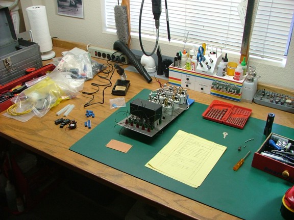
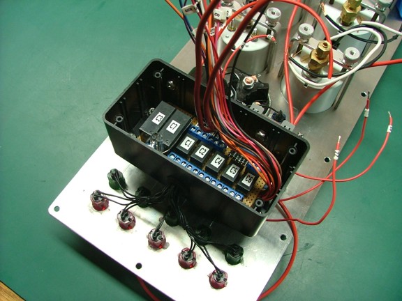
After a couple of hours designing a ladder diagram on paper I was able to start building the CIM board. It didn’t take long to finish the board which was relatively simple compared to the ECU “logic” I had to deal with before. You will notice the mercury switch that is mounted to the left side of the board below (glass tube). This switch is connected to the tip switch timer which will help the mercury switch detect a true tip-over scenario.
If the GRV-2 jet bike should fall over while either riding the bike or just running it on the kick stand it will shut the engine down for obvious reasons. The switch timer will help prevent false alarms that may be caused by intermittent switch activation due to the bike moving over bumpy surfaces.
|
|
|
 |
|
|
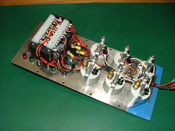
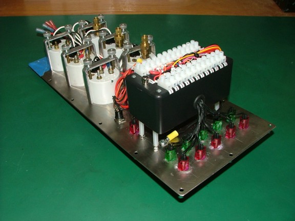
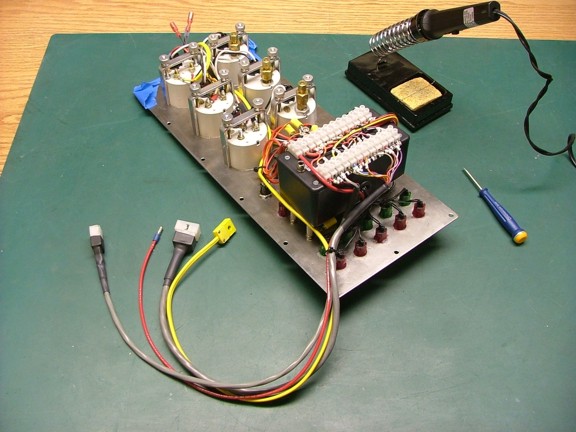
Once I was happy with the CIM boards tested operation it was mounted into it’s plastic enclosure. The CIM enclosure is mounted directly to the gauge plate as seen below.
|
|
|
 |
|
|
Terminal strips were mounted to the CIM enclosure cover and connected to all of the devices supported by the CIM. Included on the terminal strips are future connections for auxiliary devices and an afterburner enable control circuit. If I should decide to add an AfterBurner (AB) it will be necessary to provide a means of control which includes an enable circuit. The enable circuit tells the AB system that the engine is running and ready for an AB burn.
|
|
|
 |
|
|
 |
|
|
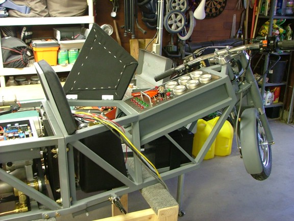
At this point the CIM and gauges need to be connected to the engine. This will be done with a wiring harness that is designed to be easily disconnected from the engine should service be required.
|
|
|
 |
|
|
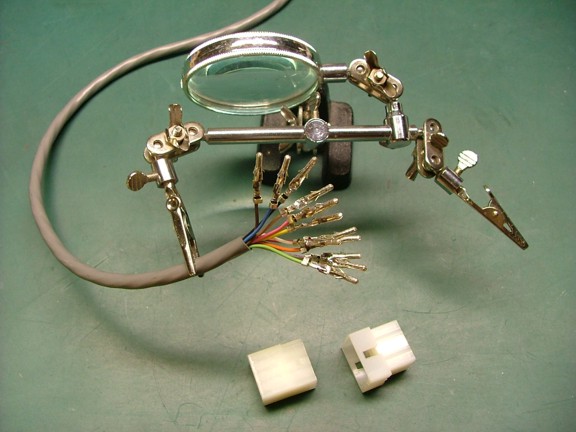
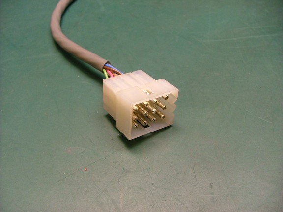
I will be using “Molex” connectors to disconnect the multi-conductor cables from the ECU should the panel or frame need to be removed. These connectors are really versatile and allow the user to configure the plug as needed.
|
|
|
 |
|
|
I soldered the connector pins to the multi-cable and then installed them into the Molex connectors.
|
|
|
 |
|
|
 |
|
|
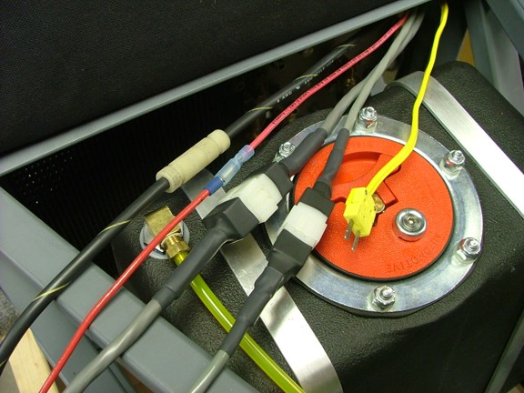
I used some heat shrink tubing to cover the backside of the connectors as seen below. You will notice that the thermocouple wire on the right has a special connector. This “Omega” style connector is specifically made for type “K” type thermocouple wiring. You can find them on eBay with the key words “thermocouple connector”.
|
|
|
 |
|
|
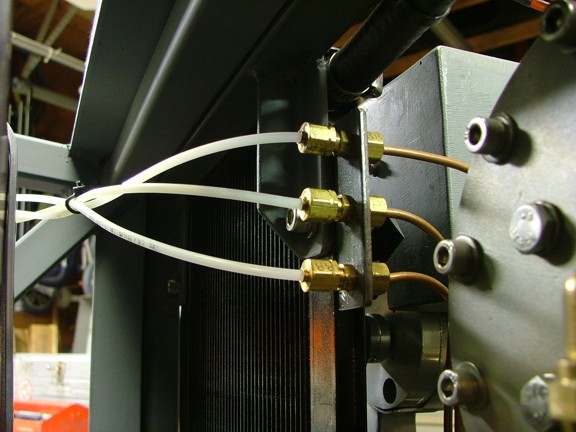
The pressure gauges will be plumbed into the engine with the use of 1/8” nylon tubing. The engine has a pressure tap manifold on the front where the tubes attach to (seen below). This manifold will serve as the disconnect point should the front frame need to be removed from the engine.
|
|
|
 |
|
|
The newly completed wiring harness was attached to the CIM terminal strips.
|
|
|
 |
|
|
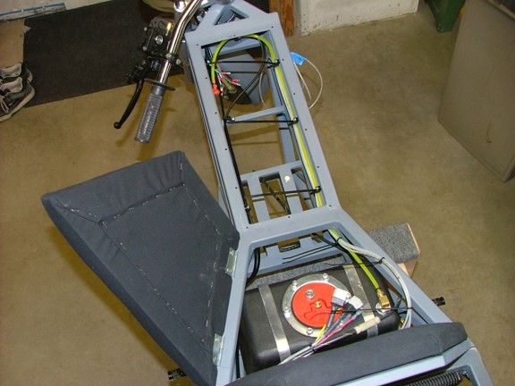
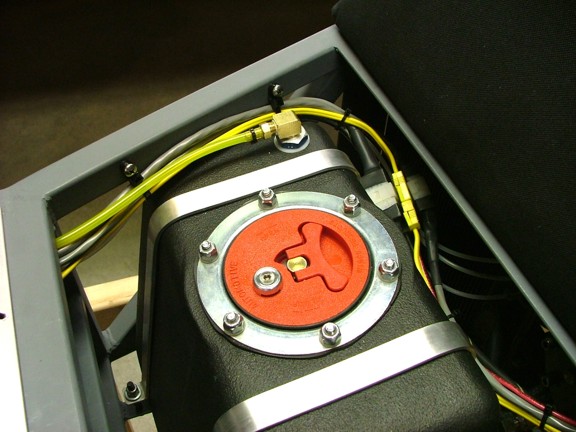
Some “fastener-mount” cable ties were used to secure the vent tube and 1/8” nylon pressure tubes up the side of the frame beam. This will keep them out of the way when installing the gauge plate.
|
|
|
 |
|
|
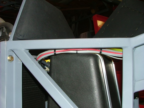
A couple of more cable ties were used to tame the wiring harness under the seat.
|
|
|
 |
|
|
 |
|
|
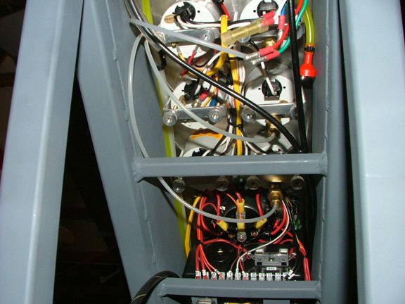
Last but not least, I attached the pressure tubing to the gauges.
|
|
|
 |
|
|
The battery was connected to the ECU of the engine and a function test was performed on the CIM unit. Everything checked out on the CIM so the next step was to see if the engine would run.
|
|
|
 |
|
|
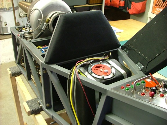
I rolled out the GRV-2 and proceeded to turn the ignition key on. Oil pressure was steady at 35 PSI and the fuel pump was making 95 PSI. All of the gauges seemed to be working perfectly and the indicator lights were giving me a green on oil pressure and fuel pressure. I momentarily twisted the key to start mode and “click”, off she goes :0)
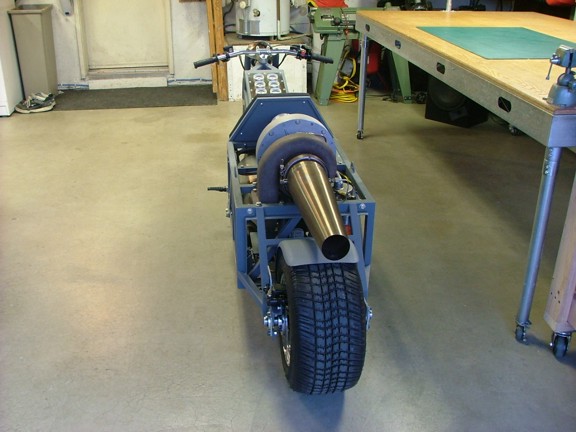
The engine spooled up to starting RPM as the pilot burner warmed up the oil system. At this point I have a green light on the photocell burn sensor and I am waiting for the minimum RPM indicator to “green out”. Once again I hear a “click” and the engine spools up to 100%. Once the engine reached idle speed the start indicator light switched off and the engine was in run mode :0)
|
|
|
 |
|
|
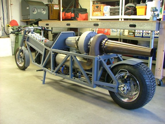
Now that the engine was running I had the chance to see how much it would push the bike while I was on it. I moved the bike to about half way down the driveway and then throttled up to full power. The bike pushed me up the driveway and was gaining speed as it headed for the back door!!! Well, I guess that answers the question of it being able to move on it’s own power :0)
|
|
|
 |
|
|
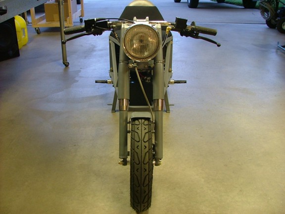
I weighed the bike using a scale from the bathroom and placed it under each wheel (not shown). The total weight came out to be 295 pounds with the fuel tank empty. Knowing this information along with a good feel for how much thrust it has is a good sign that the bike will indeed be faster than my Turbo Tug :0) I still don’t really know how fast it will go until I get it on the dry lake bed (where I plan to test the bike).
I am guessing the bike will hit 35-40 MPH without an afterburner system. If the bike does not perform to these expectations I will build an afterburner to augment the thrust a little. Either way, the bike is going to move :0)
|
|
|
 |
|
|
I now need to organize my trip up to the desert for the bike’s trial run. I will need a few people to help out so I must synchronize everyone’s schedules to align on a good day to test. In the mean time I can tinker on the details of the bike like planning the paint job or fine tuning the brakes & wheel bearings. Needless to say I am very excited !!!!! :o) I just have to hope for good weather now :op
Please join me again for the continuation of the GRV-2 project!!!!! Till then be safe my friends.....
Don R. Giandomenico
|
|
|
 |
|
 |
|
 |
|