|
With only a brief idea of what I was going to build, I set out to buy the steel to construct the GRV-1. I hit the local steel supply and picked up 40 feet of 1-3/4” .060 square tubing, 60 feet of 1” .060 square tubing, 10 feet of 1-3/4” .090 square tubing and a 8’ X 4’ sheet of 16 gauge sheet steel. I figured that I would start with more than I need and stockpile the rest for future projects. Earlier I had purchased some go kart parts online to help me build the kart including tires, wheels, disc brakes, sprocket, axle, bearings, tie rods, and spindles.
|
|
|
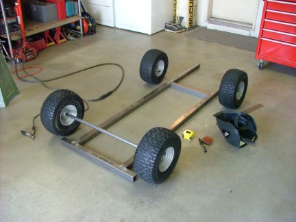
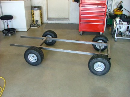
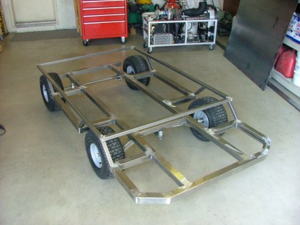
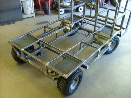
The typical way I design things is to start with an idea in my head and then start building. I cannot lay out everything on paper as it does not agree with my creative process. Needless to say, not all my ideas work but I can better visualize the idea if there is something real to look at. To help me design the GRV-1, I built a basic rolling chassis that I can build off of. This is all I needed to kick start the process of creation.
|
|
 |
 |
 |
 |
 |
|
 |
 |
|
 |
 |
|
 |
 |
 |
 |
 |
|
 |
|
 |
|
|
 |
|
|
|
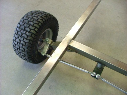
By utilizing the go kart spindles, I made a “trailing” tie rod steering linkage that will later be connected to a gearbox for the steering wheel. The trailing system allows me to incorporate geometry to correct for turning radius differential. I am hoping that the go kart spindles are strong enough to handle my proposed gross weight of 500 pounds and if not I will make my own spindles later. The front cross brace is made from 1-3/4” .090 steel and the rest if the frame is .060 thick to save weight. Hopefully I will be able to keep the overall weight down and not build a tank.
|
|
|
|
 |
|
|
|
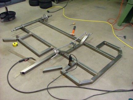
Knowing a little better what I was going to build I set out to complete the sub frame of the kart. By using my handy horizontal band saw, I cut out the mitered pieces for the side rails and front bumper. I used .060 thick steel for these as well keeping the weight down.
|
|
|
|
 |
|
|
|
 |
|
|
|
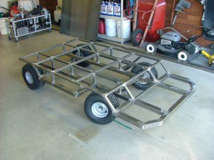
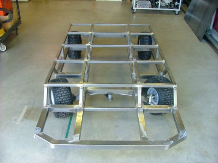
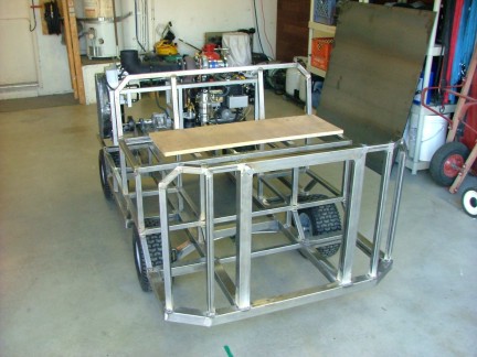
This part of the project was a few hours of work with careful welding as to not warp the sub frame before it is mated to the platform. With even more of the frame complete, I had a better idea of what this thing was going to look like. After a short brake I set out to build the platform that the engine will be mounted on. I used 1” .060 square tubing to build a platform that is elevated just above the wheels. This platform will help strengthen the chassis and be a point to attach equipment to.
I “got all crazy” with the band saw in the “bat cave” and cut up all kinds of pieces as the creative fluids wer-a-flowin’. Man this stuff is fun!!!
|
|
|
|
 |
|
 |
|
|
 |
|
|
|
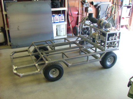
With the frame tacked together (as to prevent warping) I test fitted the GR-5 to the back to check for alignment. I matched the framework of the platform to the width of the GR-5 frame so I could use through bolts to hold it to the platform..
|
|
|
|
 |
|
|
|
 |
|
|
|
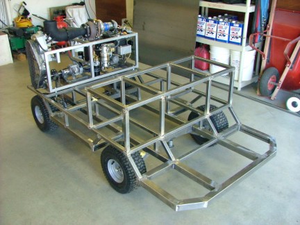
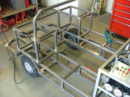
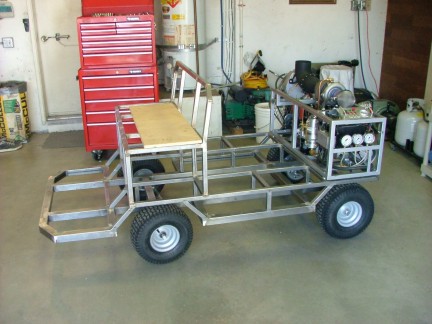
So far, so good!!! By now I have a few days and 20 hours into the project. The progress I was making kept me motivated but my supportive wife Stacy made it possible. I am very lucky to have such a cool wife that will allow me to work on stuff that she doesn’t relate to. Those of you who are married understand what I mean :0} After taking care of other business, I got back to work on the bench seat for the GRV-1. I used the 1” square tubing to build a box frame that will hold the seat for the driver and one passenger.
|
|
|
|
 |
|
|
|
 |
|
|
|
 |
|
|
|
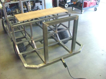
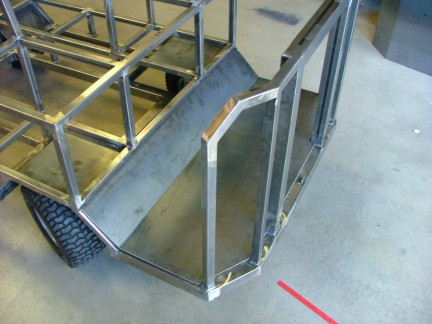
With the completion of the seat, it was time to build the knee guard which will house the control panel. I wanted to make the front end sturdy enough to handle a minor collision and not fold in on the drivers legs. I welded a super strong bumper/knee guard to the sub frame utilizing both 1-3/4” tubing and 1” tubing. This thing is starting to get heavy which worries me. I cannot expect the 6 HP GR-5 engine to push this thing very fast if it is too heavy.
|
|
|
|
 |
|
|
|
 |
|
|
|
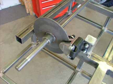
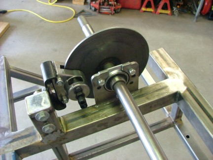
At this point I opted to finish the disc brake installation and welded the caliper bracket to the sub frame. This mechanical caliper will connect to the brake pedal with a steel control rod.
|
|
|
|
 |
|
 |
|
|
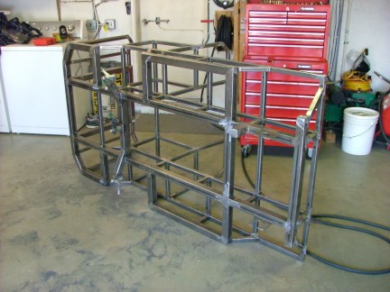
I wanted to do most of the frame fabrication and tacking before I final weld all of the pieces on the platform. This along with “alternating” my welding will keep the frame as straight as possible. After the majority of parts were tacked onto the frame, I final welded the entire frame. I used my angle grinder and flap disc to grind off the welds on exterior sides of the frame to give it the “finished look”. This process took about 4 hours to complete and I needed a break. I must of swept up about 3 pounds of metal off of the floor!
|
|
|
|
 |
|
|
|
Having the bulk of the framework complete, it was time to put her back on her feet so I bolted the wheels back on and continued. I needed to make some wheel wells to prevent FOD from being thrown up into the engine so I used the sheet steel and built them to fit. I also needed to make the floor pan and knee guard from the sheet steel so I carefully measured and cut them to fit as well. To make my bends in the sheet steel, I used a grinder to score the back side of the sheet allowing it to bend at the score.
|
|
|
|
 |
|
|
|
 |
|
|
|
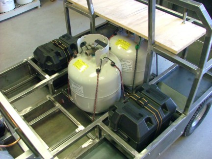
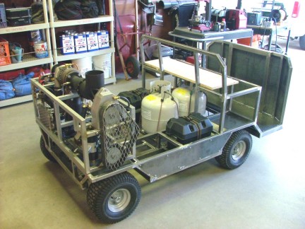
I had to make some brackets to hold the propane tanks so I fitted them to fit into the void in the center of the frame. The tanks will sit in tank cradles and be held in place with Bungee cords. I will be using two tanks but I had left enough room for three. I test fit the engine and tanks to the frame so I could visualize where I am going with my design. After looking at it a while, I added a couple battery boxes in the side compartments. One box will be used for a car battery and the other will possibly be used to hold test equipment.
|
|
|
|
 |
|
|
|
 |
|
|
|
By now I have 50+ hours of work into this project and expect at least 50 more before completion. I still have the steering, pedals, seats, control panel, fuel system, and drive train to work on to complete the GRV-1. My wife Stacy whom worked for United Airlines previously, looked at the GRV-1 and said that it looked like a aircraft tug. This prompted me to nickname the GRV-1 the “Turbotug” and so it shall be! I hope to get the Turbotug together in the next few weeks so I can cruise down the street in my own SUT- sport utility turbine :0)
Wish me luck, until the next episode............
Don Giandomenico, Exhausted Fabricator.
|
|
|
|
 |
|
 |
|
 |
|