From the beginning of the GR-7 project I have been tossing around different ideas for a starter drive coupler. For a while I was planning to use a twelve-point socket attached to the mainshaft that would engage to the stock 1/2-20 compressor nut. Unfortunately this setup would have a relatively large rotating mass with the weight of the socket and thus be more of a liability at high RPMs. What I really
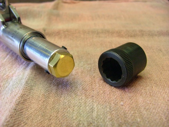
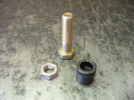
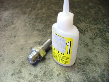
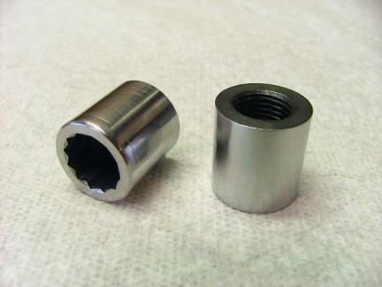
wanted was a system that would have a low rotational mass making it easier to balance and less of a danger at high RPMs. One day while looking over McMaster-Carrs catalog I stumbled on what is called an Allen nut. One end of the nut has female threads and the other has a twelve-point broached Allen socket. The Allen nut is designed to be used in areas where a standard socket will not fit as in a tight countersunk position. When I saw the Allen nut a incandescent lamp illuminated brilliantly above my cranium :0) I could use the Allen nut as a replacement for the stock compressor nut and drive it with a brass hex-head bolt. This system would greatly reduce the danger of a SAE socket being choked down by the VT-50 at 30,000 RPM !!! The brass 5/16-18 bolt could also act as a shear point in case the mainshaft was to seize. It all seemed to make sense but would it work? I purchased five 1/2-20 Allen nuts from McMaster (#92067A033) and a box of 5/16-18 X 1/2 brass bolts for the hex-drive adaptor.
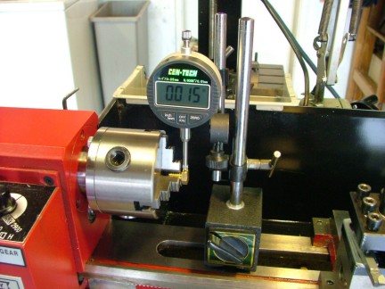
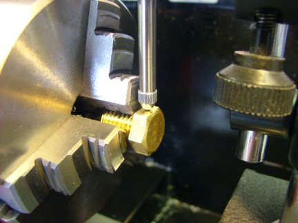
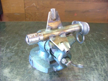
I noticed that the brass bolts I had purchased were not all created equal. Some of them had a wobble on the hex-end when rotated axially. I decided to check through the lot to find the truest ones in the bunch. I used a dial indicator to test the low spots for equality on the flats of the hex-heads. After a few minutes of testing I weeded out about 3/4 of the box. I installed one of the straight brass bolts into the mainshaft adaptor and tightened down the set screws. Once again I used blue threadlocker to hold the set screws tight.
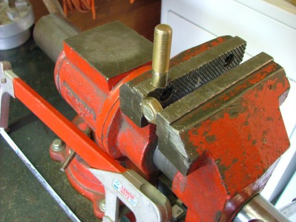
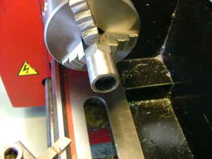
The next step was to go through the Allen nuts to see if they had any wobbles in them as well. To do this I would need a test arbor to mount to the lathe chuck that would replicate the turbine shaft. I had a 1/2-20 bolt that looked like it would work so I chopped off the hex-head and machined one end smooth on the lathe.
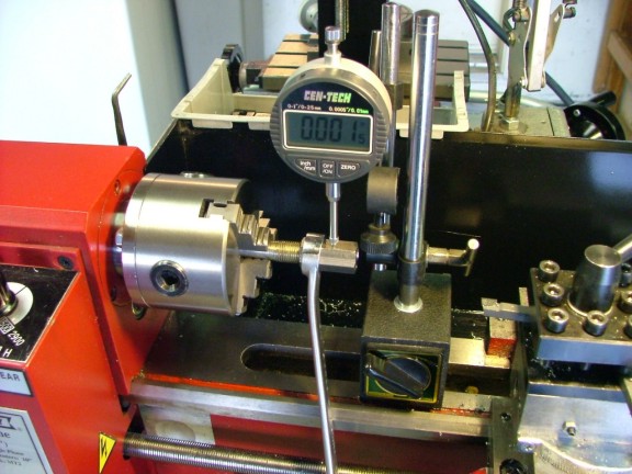
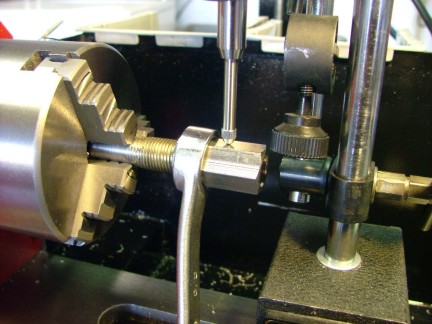
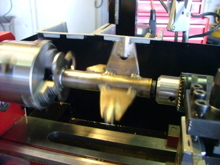
Many hardware manufacturers use a process of rolling a blank bolt through a set of parallel dies to create the threaded portion of the bolt. This is a quick and efficient way of forming the threads but can leave waves in the face of the threads. I had to check for inconsistencies in the depth of the threads before I could trust the test arbor to be axially true. I used a 1/2-20 rod coupling and a dial indicator to see if the threads had any runout before I continued. Notice the box-end wrench I used to hold the rod coupling from spinning as I rotated the lathe chuck.
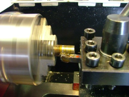
After verifying that the threads were straight I glued on a 1/2-20 standard nut to the test arbor with super glue (which can also be used as a super- strength threadlocker :0). Using the lathe I machined a clean face on the bolt completing the test arbor.
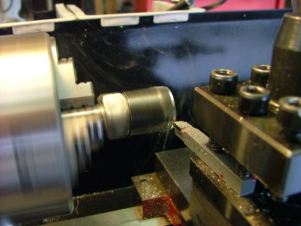
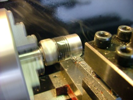
I screwed on all five of the Allen nuts, one at a time and tested them for wobble. Unfortunately three of them were obvious rejects as the Allen broached end had a slight wobble when rotated on the test arbor. The two straight nuts were mounted back onto the test arbor and trimmed round to improve balance.
While still on the lathe I polished the Allen nuts with a metal polish to prepare for the next procedure.
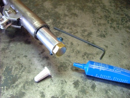
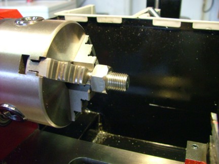
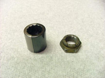
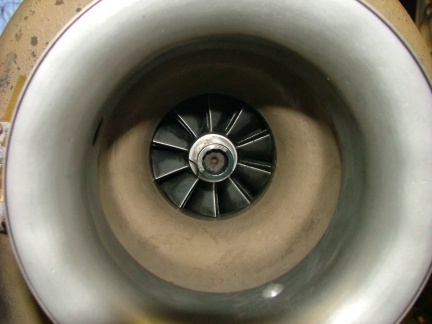
later in the build I plan to use a photo-eye tachometer to test the RPMs of the GR-7. As to facilitate the use of the reflective photo-eye sensor I decided to use a gun blueing chemical to darken half of the new compressor nut. This is similar to what I did on the GR-1 project. Once the chemical had blued the steel nut I painted it with a clear polyurethane topcoat. (See addendum) Notice the old compressor nut to the right of the Allen nut below.
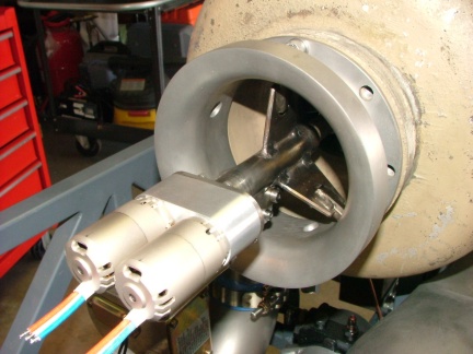
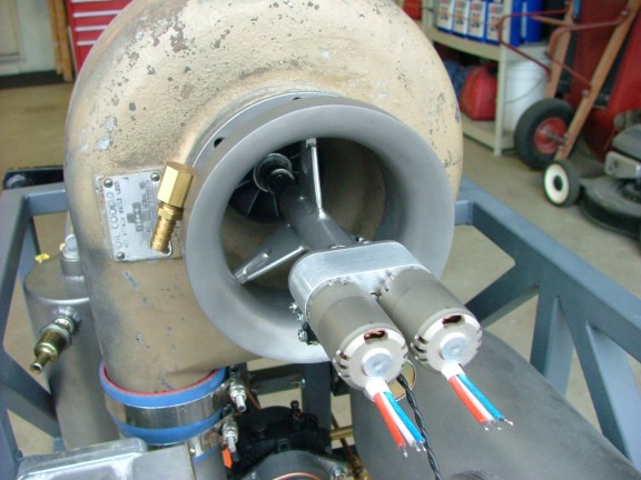
The stock compressor nut was of a self-locking variety where as the new Allen nut is not. Because of this a threadlocker compound must be used to prevent the starter motor from unscrewing it from the turbine shaft during starting. The probability of the Allen nut coming loose when the engine is running will be low as the turbine shaft rotation is in the direction of tightening the nut. With the Allen nut in place on the turbine shaft (loosely) I was able to temporarily test fit the starter into the drive coupling.
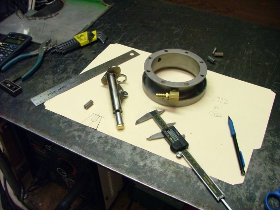
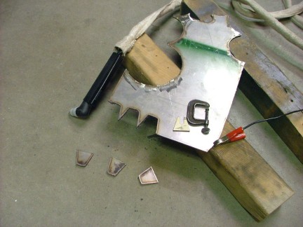
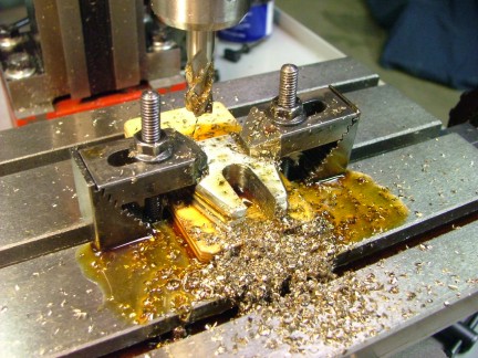
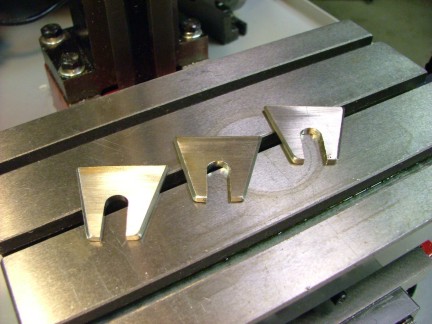
I now had to design a set of support brackets that would hold the starter assembly inside of the bellmouth. I used a card stock template to cut out a 1/8 plywood guide for the plasma cutter and proceeded to cut out three starter supports.
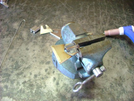
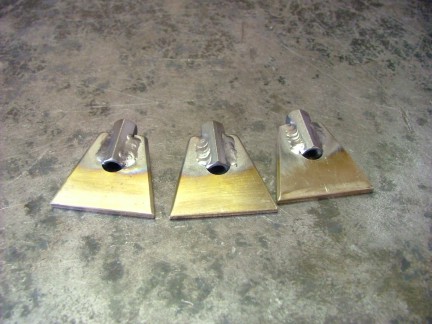
Once the brackets were cut out they were ground smooth in preparation for milling. A slot needed to be milled into one end of the brackets to accommodate the stainless 1/4-20 rod couplings that will be used as threaded inserts. The slots were cut on the mill and the rod couplings were TIG welded into place.
The starter brackets were welded onto the mainshaft tube 120 deg. apart. A socket was inserted into the turbine-end of the mainshaft tube during the welding process to help prevent heat warping.
The turbine-end of the mainshaft tube needed to be cleaned up with the Unibit as there was still a small amount of warpage.
I assembled the mainshaft to the gearbox so I could lay out the mounting holes in the bellmouth. Once the holes were drilled the starter was disassembled and the mainshaft tube was sand blasted.
The freshly sand blasted mainshaft tube was then bead blasted with a fine glass bead. This surface treatment leaves a nice silver-gold finish to the metal.
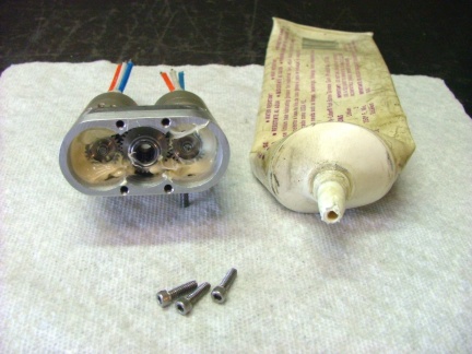
The tube was cleaned thoroughly and the parts were reassembled carefully.
The gearbox was packed with a lightweight grease and assembled.
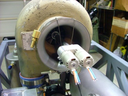
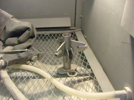
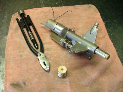
All of the hardware on the starter has to be secured as to not be ingested by the engine. Threadlocker, Nylock nuts or safety wire was used to prevent the hardware from loosening. The gearbox backplate hardware has special safety wire holes drilled through their caps. I used a stainless steel tie wire to secure these bolts in place. Notice the safety wire pliers, they help to twist the safety wire as needed.
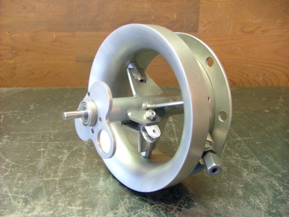
For the most part the starter is complete. A final alignment check was all that was left to do.
I am eager to see if this contraption will start the engine or not. I should be able to test it soon enough but I still need to clean up a few loose ends before a proper testing session can be conducted. I hope you will check back to see the continuation of the GR-7 project.