|
|
 |
 |
|
Posted on June 6, 2004
Well I am back at it again! I have put some time into getting together the parts to build a power turbine for the GR-1 turbojet engine. The power turbine or “free-shaft” turbine will convert the turbojet into a turboshaft engine where rotary power can be yielded from the engine. The new experimental turboshaft engine will be called the GR-5. My goal is to create a low-speed power turbine that can be made from inexpensive and available materials.
|
|
|
 |
 |
|
The basic design of a free-shaft turboshaft engine incorporates a gasproducing section (the turbojet) and a power turbine. The gas producing section creates a high volume of pressurized gas which is directed through a power turbine that is not on the same shaft as the gas producer turbine (the turbocharger). The separation of the two drive shafts allows for a torque conversion that is easier to manage than a single shaft gas turbine. If for any reason the load on the “free-shaft” turbine slows down the power turbine, it will less likely stall the gas turbine as a single shaft gear drive turbine may.
I am designing the turboshaft conversion to bolt onto the exhaust of the GR-1 engine allowing me to utilize the current engine configuration. The basic design of the GR-5’s power turbine will consist of a axial flow stator and rotor housed in a chamber. This chamber will allow me to easily exchange different stator sections and rotors so I can optimize my design through trial and error. The turbine housing will be mated with a 5:1 inline gear box that will reduce the proposed turbine RPM of 15,000 to a useable RPM of 3,000. I am trying to design the power turbine to create torque at low RPM so I can utilize cheaper turbine wheel design and reduce the explosion risk of a high-speed turbine.
Most commercial turbine wheels are made of expensive and rare alloys which make it very hard for the do it yourself crowd to design one. Although there are a few that have access to the tooling and materials to build a professional turbine wheel, I am not one of them so I must engineer a low cost turbine wheel for my purpose. I hope to build the turbine wheel out of welded mild steel opposed to a casting. This design will be the cheapest but if it fails, I will consider researching how to cast my own turbine wheel.
I started my project by designing the turbine housing which will direct the rushing gasses through the stator and turbine wheel. The housing must also direct the exhaust gasses away from the mated gearbox and hopefully shield it from excessive heat. My design converts the turbo’s reverse-radial flow ducting to an axial flow housing by expanding the flow to meet the turbine wheel vanes. This will be done with a cone shaped diverter suspended in a expansion duct. The diverter cone will be supported by the stator section and will force the gasses around the face of the drive shaft and turbine wheel hub.
|
 |
|
|
 |
 |
 |
 |
 |
|
 |
 |
|
 |
 |
 |
 |
|
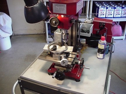
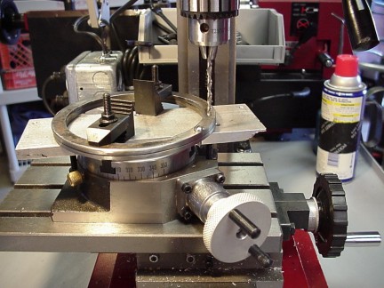
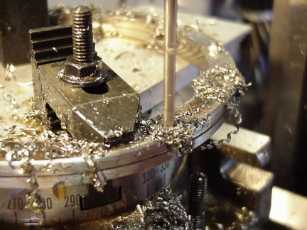
By using a rotary table in conjunction with my mill, I was able to index and drill 12 holes into the rings for my flange bolts. This worked really well and was a lot of fun to do. By turning my rotary table 30 degrees at a time, I could evenly space my holes in the flange. Having the right tools is very cool!
|
|
|
|
 |
|
 |
|
|
 |
|
|
|
The finished flange plates are ready to be welded into place.
|
|
|
|
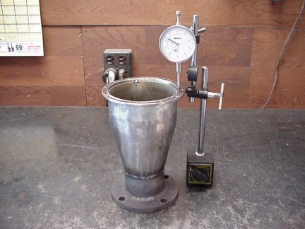
I am now ready to test fit the flange to my expansion duct. By using a dial indicator and my work bench, I can test the flange for it’s trueness to the opposing flange.
|
|
|
|
 |
|
 |
|
|
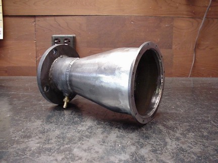
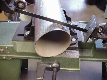
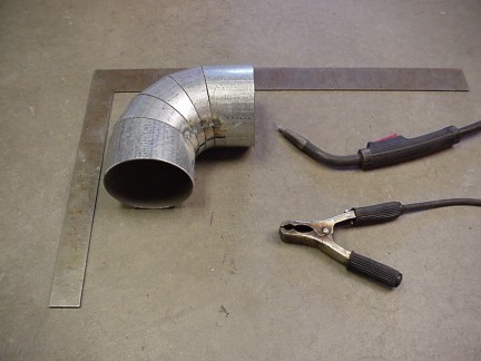
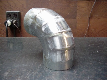
After some adjustment, I welded the flange on the expansion section. By using this flange type system, I can access the turbine wheel and stator for inspection and exchange. I am now ready to fabricate my exhaust diverter/turbine housing. By using my horizontal band saw, I cut 8 - 11.25 degree cuts in my 4” EMT to create a 90 deg. elbow as to be used to divert the exhaust flow away from my gearbox.
|
|
|
|
 |
|
 |
|
|
 |
|
 |
|
|
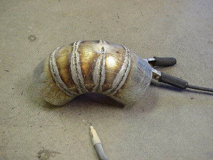
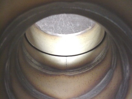
Once the segments were checked and squared, I welded them together. I used a section of pipe to double up the steel thickness where the turbine wheel will be for use as a “scatter shield”. The scatter shield will hopefully contain any steel fragments that may fly off my experimental turbine wheel in the event of a failure.
|
|
|
|
 |
|
 |
|
|
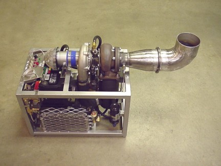
After some trimming, I was able to weld on the second flange completing the flange system. I will use 8-32 stainless hardware to bolt the sections together. To get the flanges to mate flat, I used my belt sander to surface the flanges after they were welded. I am now ready to test fit the housing to the GR-1 and get an idea where all of my parts will be located.
|
|
|
|
 |
|
|
|
 |
|
|
|
The next step in the GR-5 project is to make and install the drive shaft heat shield. The heat shield will protect the drive shaft tube and bearing from the direct heat of the turbines exhaust.
Till next time,
Don Giandomenico
|
|
|
|
 |
|
 |
|
|