Hello again folks!!! Its been a long time since Ive had a chance to work the GR-7 project. In fact it was 32 months ago that I took a break from the experiment to work on other projects. Since then I have completed several hobby and non-hobby projects including my Top Flite B-25 project as well as a much needed kitchen remodel/house painting project at my home. Now that I have some free time to burn it is only appropriate for me to revisit the GR-7!!!
Before I could do any useful work to the GR-7 I needed to reacquaint myself with the workings of the engine. I spent some time looking over the condition of the engine including the starter mechanism and the hydraulic system. After a brief charge of the battery I spooled up the engine for a test run to see if I could get it to run. Amazingly the engine fired right up and ran smoothly on the first try. Once the engine had cooled down I proceeded to remove the starter motor speed controls in preparation for the first task to be worked on.
My original plan for the continuation of the GR-7 was to patch together a working tachometer so I could report some test data including thrust and RPM readings. Since then I have concluded that a working ECU (Electronic Control Unit) is a more important goal to achieve prior to bench testing the GR-7. The ECU will help regulate most of the functions of the engine allowing me to pay closer attention to test data and not running of the engine. The design and building of the ECU will be a challenge considering it will be twice as complicated as the GR-5A ECU. The new ECU will have several new devices to control including the electric starter and photo eye burner control. However the basic function of the ECU will be the same in that it will safely control the burning of fuel and insure that the hydraulic system is working properly.
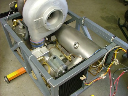
Before any work could be done on the design of the ECU system I need to install an appropriate housing for the electronics. Having an ECU box in place will allow me to lay out where the electronics will fit in the enclosure. Removing the starter assembly cleared a path for me to see where the box will mount. An 8 x 8 steel electrical pull box seemed to fit in the unused space above the oil pump but would need a little modification to fit.
I wanted the ECU box to be flush with the top edge of the engine frame so some fabrication was needed to tub out the bottom to clear the oil pump motor. You can see below where the oil pump motor holds up the box.
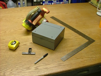
Carefully using a circular metal saw I cut out a section of the new ECU box. A straight edge was clamped to the box and used as a fence to insure a straight cut.
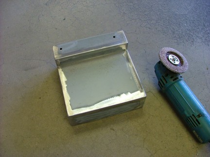
Using a piece of scrap metal (large pull box cover) I was able to make a bottom plate for the ECU box. I tack welded the plate in for a test fit and clamped the box in the engine frame for a test fit..
I tested the effect of the box location in relation to the flow of air through the oil cooler fan before deciding on a permanent location for the box. Luckily the air flow was minimally effected by the presence of the box behind the fan blades. My plan was to situate the ECU box near the fan to promote laminar air flow around it in an attempt to keep it insulated from the hot engine parts. Vent holes could also be added later to the front of the box allowing the oil cooler fan to force air though the enclosure. This could help cool the speed controllers if needed later on.
A support brace was now needed to hold the rear of the ECU box. I installed two mounting tabs to the sides of the engine frame to support a new bracket as seen below. Notice the wet towel used to catch any welding slag which sticks incredibly well to stainless parts :0/
I fabricated a box support bracket out of 1 angle iron and then bolted it to the mounting tabs as seen below.
Now that I was happy with the box location I could finish welding up the seams on the box. I left the two holes on the bottom open as to serve as drain holes in the event water gets in the box (hopefully not :0).
An 80 grit flap disc was used to smooth out the welds and really tune up the appearance of the box.
A set of 8-32 stainless screws were used to bolt the box to the angle iron.
I also fabricated a forward support for the ECU box as seen below.
It was now time to make a cover for the ECU box. I used a large pull box cover to fabricate the 8 x 10.25 ECU box cover plate. The cover is longer at the front to cover the oil cooler fan blade. I had cut my fingers up a while back by accidentally grabbing the engine frame above the oil cooler with the fan running....Ouch!!!! The spinning blades cut my fingers pretty good so I wanted to prevent that from ever happening again by covering the exposed fan blades...Duh!!!
I layed out eight holes for the cover screws and drilled them through with the cover in place. I then tapped out the box holes for 8-32 threads.
The holes in the cover plate were widened to accommodate the 8-32 screws. The cover was then test fitted into place with the stainless screws.
Now that the ECU box was complete I could put a clean coat of automotive primer on the whole assembly to prevent rust.
Before I moved into the ECU phase of the build I decided to take care of a couple of items that I would have to finish before testing of the engine anyway. One of these items is the FOD (Foreign Object Damage) screen. This screen is an important safety item that prevents objects from being ingested into the engine. To prepare for the install of the screen I needed to reroute the starter motor wires through the bell mouth bottom to allow the screen to be removed and replaced.
First off I installed six new silicone power wires to the starter motors which will pass through a hole in the bell mouth. I used a set of Novac (Cat #5514) #14 gauge silicone power wires for these motor wires. Silicone power wire is the very best type of conductor for low voltage/high current applications.
I then drilled a hole in the bell mouth and installed a rubber grommet to protect the starter wires as seen below.
A set of two conductor cables were wired into the starter shaft engage switch and solenoid at this time as well. These cables will join the starter cables through the grommet.
Once all of the cables were grouped together I installed a piece of shrink-wrap to hold all of them together as seen below.
The next steps are to install the tachometer sensor tube and fiber optic unit as well as install the FOD screen. Once these items are complete I can build the ECU and ultimately test the GR-7.........Finaly!!!
Thanks for checking out my project and stay tuned for the next chapter!!