 |
|
|
|
|
|
|
|
|
|
|
|
|
|
 |
|
|
|
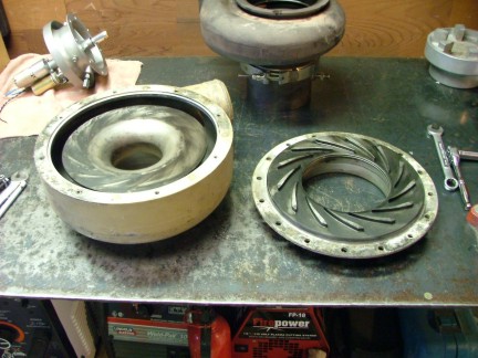
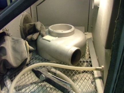
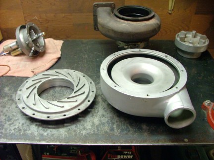
I decided to remove the tan colored paint from the compressor housing while I had the turbo apart for inspection. I removed the paint by sandblasting the housing and diffuser plate. Once the paint was removed I followed up the process by bead blasting the housing with a fine glass bead to give the metal a matte finish. The housing was then cleaned with a solvent and reassembled.
|
|
|
|
 |
|
 |
|
|
 |
|
|
|
The next step was to inspect the turbine shaft bearings and seals for problems. Luckily the VT-50 is an incredibly simple turbo to disassemble with a low part count. I simply removed the compressor nut and carefully pulled out the turbine shaft. The turbine shaft has an oil seal on either end of it comprised of a set of rings much like you would find on a piston of an IC engine. Two rings seal the hot end and one ring seals the compressor side.
The cool end seal rides in a removable ring land which is sandwiched between the shouldered neck of the turbine shaft and the compressor wheel. This removable ring land also serves as a thrust bearing surface which comes in contact with the end of the hydrostatic bearing. The hot end rings are set in ring lands that are machined into the turbine shaft alloy itself. This ring land also serves as the opposing side thrust bearing surface for the hot side.
Both sets of rings looked good and had an ample amount of spring tension (a good sign that they had not been damaged by heat).
|
|
|
|
 |
|
|
|
I am amazed at how heavily built the rotating assembly is on the VT-50. This is no lightweight turbo as the turbine wheel and compressor weigh in at 3.67 pounds. Thats a lot of energy spinning at 66,000 RPM !!!
|
|
|
|
 |
|
 |
|
|
I proceeded to inspect the bearing and shaft surfaces for wear and damage. I was happy to find the bearings in very good shape and the shaft was in great condition.
|
|
|
|
 |
|
|
|
 |
|
|
|
I applied some motor oil to the bearings and reinstalled the turbine shaft. I situated the ring gaps on the hot end at 10:00 and 2:00 oclock with the turbo drain at 6:00 oclock. This is to minimize oil leakage through the seal. I also installed the cool end rings gap at 12:00 oclock for the same reasons. After shutdown the oil will flow out of the oil gallery and can seep through the rings. If they are positioned with the gaps upward it will help prevent this.
After the assembly was together I applied some medium strength thread locker to the shaft threads to help keep the Allen nut tight.
|
|
|
|
 |
|
|
|
The aluminum compressor wheel will undoubtedly expand with the heat it will be subjected to while in operation. This expansion will be greater than the heat expansion of the turbine shaft it rides on due to the difference in metal composition (aluminum has a high expansion coefficient). This means that while the engine is running the compressor nut will tighten up beyond what it was torqued to originally.
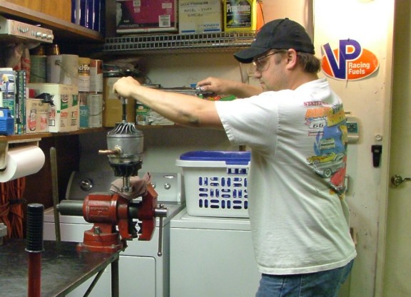
Being aware of this I torqued the Allen nut at a conservative 30 foot-pounds. Installing the nut too tightly could result in shaft warping when the engine heats up. Notice the ratchet in the vise holding the 12-point nut on the end of the turbine wheel.
|
|
|
|
 |
|
|
|
Being that I have disturbed the original installation of the compressor wheel, balance may have been compromised. I made an attempt to orient the compressor wheel exactly as it was removed (rotationally) as to preserve the overall dynamic balancing but this is no guarantee that the new Allen nut wont induce vibration at certain speeds. Unfortunately I do not have a dynamic balancing machine (yet :0) so I will run the turbine as-is and closely monitor for any vibration.
My long term plan is to build a home-brew dynamic balancing machine which will come in handy especially if I intend to further my research.
|
|
|
|
 |
|
|
|
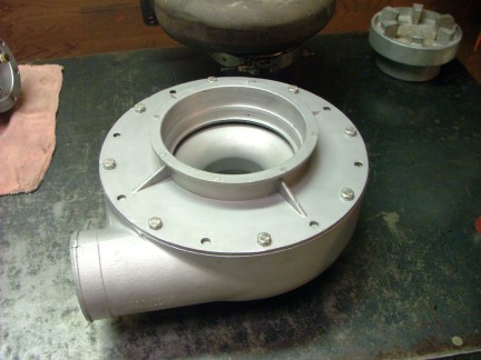
I reassembled the turbo and installed it back into the engine frame in preparation for testing. Quite an improvement from the tan paint job !! :0)
|
|
|
|
 |
|
|
|
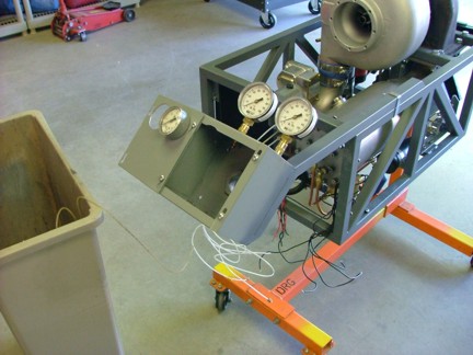
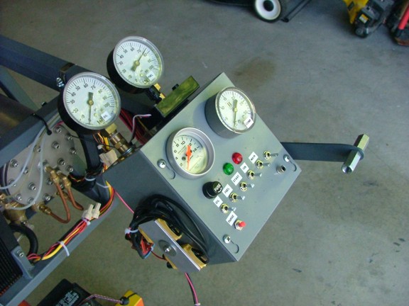
The next step was to fabricate a temporary control panel to operate the GR-7. I needed a basic control panel to mount my gauges and house the miscellaneous control switches I will use to run the engine. I welded up a bracket that attaches to the engine frame and supports a 6 x 6 metal enclosure. The enclosure was then modified to hold my pressure gauges and EGT gauge.
|
|
|
|
 |
|
|
|
I needed a way to control my throttle from the control panel so I designed a lever system that pulls on an aircraft cable attached to the throttle valve arm. During this fabrication I took the time to install the idle switch on the throttle valve which will eventually connect to the ECU.
|
|
|
|
 |
|
|
|
 |
|
|
|
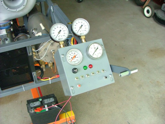
I installed a handful of switches to the panel cover which will control the hydraulic, fuel, ignition and starter systems. I then wired up the panel connecting the various pumps and solenoids.
|
|
|
|
 |
|
|
|
 |
|
|
|
I tested out the fuel solenoids and ignition system for proper operation followed by a pressure gauge test. There was only one thing left to sort out and that was the starter controllers. To drive the brushless motors I had purchased two 45 amp speed controllers which were primarily designed for model aircraft use. The speed controllers were designed to be used with a proportional radio control system which communicates with the controllers via a pulse-width signal generated by the remote control receiver.
Since I will not be using the controllers with a remote control receiver I will need to generate this pulse-width signal to control the speed of the motors. To do this I am employing a servo tester which is a device used to replicate the 1 to 2 millisecond signal for proportional radio control system testing. The servo tester will allow me to control both starter motors simultaneously with one simple control knob, no remote control interface needed.
|
|
|
|
 |
|
|
|
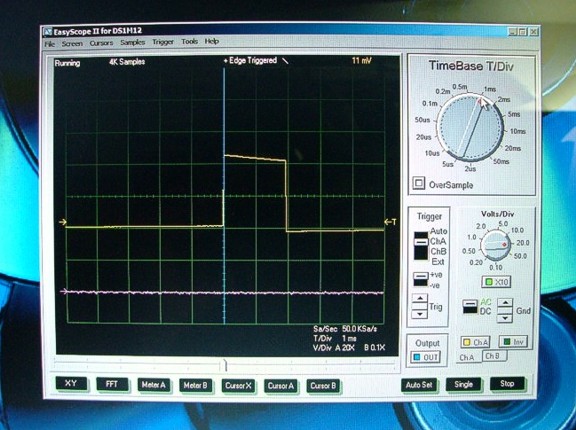
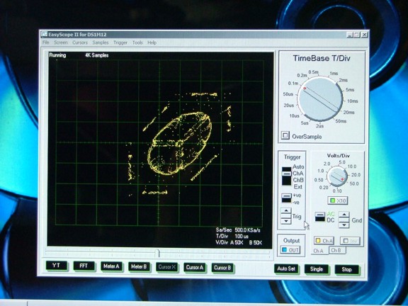
Using my PC-based oscilloscope, I tested out the signal generated by the servo tester. I measured a 50 Hz signal (20 ms pulses) with a 4.96+ volt gate 1 to 2 ms in length depending on where the control knob was positioned. This gate or pulse-width is what tells the servo or speed controller where to be on the proportional scale (-100% to +100%) in a typical remote control application.
|
|
|
|
 |
|
|
|
The two photos below show the two extremes of the signal. Each block is about 1 millisecond wide.
|
|
|
|
 |
|
|
|
 |
|
|
|
I connected the speed controllers to the brushless motors with some 12 gauge wire and then mounted the starter assembly to the VT-50. The speed controllers were then mounted to the temporary control panel with a heat sink made out of bar aluminum. This will help dissipate heat generated by the high current being processed by the controllers.
|
|
|
|
 |
|
|
|
 |
|
|
|
The speed controllers were connected in parallel to the servo tester via a servo wye connector. I used some Velcro to mount the servo tester to the top of the control panel for easy access.
|
|
|
|
 |
|
|
|
I hooked up the controllers to my 12 volt battery and tested the motors for the proper phase rotation. Once I verified the motors were spinning in the right direction I tested out the starter solenoid for a starter pretest. I hooked up my two channel PC oscilloscope to the motor leads of one of the brushless motors to monitor the controllers output. I put one channel between A and B phase and another between A and C phase.
|
|
|
|
 |
|
|
|
I ran up the motors to about 50% without being connected to the turbine shaft. The gearbox seemed to handle the speed very nicely so I ramped up the motors to a full speed test. Other than the gearbox being a little noisy it performed as expected. The photo below is of a X,Y scope reading while the motors were running at 50% unloaded. You can see the distinct 120 degree separation of the three phase signal.
|
|
|
|
 |
|
|
|
In the next test I started up the oil pump and engaged the starter solenoid for a live run. I slowly ramped up the starter motors while watching my current draw. Below is a photo of the X,Y reading at 50% loaded power.
|
|
|
|
 |
|
|
|
The sound of the turbine spooling up was giving me goose-bumps!!! I was very impressed at how cool it sounded. Unfortunately the motors were drawing a lot of current and getting very hot so I shut them down for fear of damaging the windings. The oil in the engine was just too thick in its cold state and was not allowing the turbine to spin freely. This would be a problem that I would have to fix before I could resume testing.
|
|
|
|
 |
|
|
|
I had two options to choose from at this point, lower the oil pressure to the turbo during start up or, preheat the oil to reduce its viscosity. I chose to try to preheat the oil with the ignition burner at a low RPM until the starter is able to spin the turbine freely. To perform this test I would need to hook up the fuel line and fire up the burner. Ultimately I would be attempting an actual start up test.
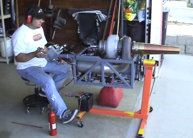
In preparation for the live fire test I attached the stainless jet pipe to the engine. The pipe will create back pressure on the turbine and in turn make the starter work a little harder during the start up cycle. I wanted to test the starter in a real world environment ensuring it will perform as expected.
|
|
|
|
 |
|
|
|
I attached the EGT (Exhaust Gas Temperature) sensor to the jet pipe and hooked up the fuel can to the fuel line. After priming the fuel pump I tested the ignition burner/circuit for proper operation. Just as before, the burner fired up reliably and on que. I proceeded to fire up the oil pump and verified 50 PSI oil pressure for the turbine bearing.
I engaged the starter solenoid and applied 20% power to the starter motors. The ignition burner was then lit to preheat the oil in the system. I could audibly hear the turbine whine faster as the oil heated up during this process. At this point the starter motors were drawing around 12 amps each (24 amps total) and dropping as the engine heated up. The motors were keeping relatively cool during the preheating cycle.
The engine was now ready for an attempt at a full start so I ramped up the starters to 50% and fired up the main burner. I had not adjusted the idle screw yet so I had to adjust the main throttle lever to achieve a proper initial setting. Meanwhile all that adjusting was heating up the motors so I shut them down and gave them a rest. After a few minutes I attempted another run, 20% at ignition and 50% with the main burner. By now the motors were drawing around 24 amps each.
The EGT was reading around 800 deg. Fahr. and the motors were cool enough so I went for it. I slowly spooled up the motors to 100% and eased the throttle up, watching the EGT the whole time. The motors peaked out at 35 amps each and slowly dropped as the turbine whined higher and higher. Sure enough, the GR-7 was coming to life!!!!
The EGT was reading about 1,100 deg. Fahr. and falling as the engine spooled up to operating speed. Unfortunately I was unable to monitor the turbines RPM as I have yet to install the tachometer sensor. I disengaged the starter solenoid and ran the engine for a few minutes. After a few cycles of the throttle valve I shut her down.
At this point I wanted to see how fast I could start the engine from a dead stop so I had my wife time the procedure. Amazingly the two little motors were able to get the GR-7 idling in about 12 seconds!!! I was so impressed by the sound I had to get out the video camera and film a start up....
See the GR-7 Starter Test Video here !!!
|
|
|
|
 |
|
|
|
I am fairly happy with the performance of the starter and very happy to move to a new chapter in the GR-7 project. I still have much to do before I can call the GR-7 a turnkey engine but for the most part all of the necessary equipment is in place. I hope to get the tachometer installed soon so I can document the operational performance of the GR-7.
At this point I have only run up the engine to 10 PSI combustor pressure and I am not sure how many PSI I will be able to expect from the VT-50 until I get the tach sorted out. Once I know my limitations I will be able to measure static thrust and publish the results. My overall goal is to produce 65+ pounds of thrust from the engine. If I cant get close to that level of thrust I will experiment with water injection or an afterburner system to compensate.
Once the engine is reliable I will start the next phase of the build, The GRV-2 Jet Bike !!! I really appreciate all of the encouraging e-mails I get and by all means, keep-em-coming :0) The very reason I spend countless hours documenting and publishing all of this info is to share my hobby with those around the world and in a way, repay the web community for giving me ideas to run with.
So thank you for visiting my humble site and I hope to see you again on the next chapter.
Till then my friends.........
Don Giandomenico
|
|
|
|
 |
|
 |
|
 |
|

