Hello again folks! This time around I am working on the piston and valve for the engine. The piston is to be machined from a piece of 1-5/8 Cold Rolled Steel (CRS) as seen below. This type of steel alloy is really easy to machine which is good in this case as I had lot of metal to remove from this part.
To start out I chucked up the steel rod in the lathe and applied some layout fluid.
Using my calipers I laid out the cut lines into the dried layout fluid. I just drug the jaws of the calipers over the dye to leave the layout marks as seen below. This is a little trick I learned from watching Monster Garage ;0)
The next step was to drill out the piston rod bore.
Using my 1/4 round carbide tool bit I carved out one side of the piston profile.
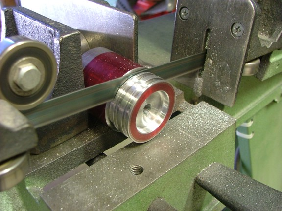
The next step was to cut the ring lands in the piston. I used a narrow carbide tool bit to cut the lands to about 1.375 in diameter.
The outer diameter of the piston was now cut to size. I cut the piston to about .001 smaller than the bore of the cylinder. This will allow for just enough clearance for the piston to properly break into the cylinder.
Now that the OD of the piston was cut I could test the fit into the cylinder. All seemed well enough with the piston fit however I had one more test to complete. I cut a small piece of Teflon ring material from the two pieces supplied with the kit. I then tried fitting the ring piece into the bore with the piston and noticed that the ring lands were too small (not shown). The ring lands would need to be deepened to about 1.365 (about .01 deeper than the prints). This is caused by the bore of the cylinder being smaller than 1.5.
I chucked the piston back up on the lathe (not shown) and cut the lands to the proper depth before cutting the piston blank off of the rod as seen below...
The piston was put back on the lathe and the other side was faced.
I used my 1/4 round tool bit to carve out the other side of the piston face as seen below...
The piston was now complete!!! I bolted the piston to the piston rod for a fit check in the engine.
The cylinder was bolted onto the frame so the piston could be tested in the bore. I was happy to see the piston cycle freely down the bore without binding.
I was happy with the fit of the piston so I chose to apply Locktite to the threads of the piston rod before tightening the piston in place. The locktite will help seal the piston/rod joint and keep it from separating later on (at least I hope :0). I shouldnt have to remove the piston again from this point out.
The next step was to cut and install the Teflon rings into the piston. I laid each ring into the lands and then cut them to length so they just touch ends.
The newly cut rings were installed into the lands at 180° apart (the ring ends). I then tested the piston for clearance in the cylinder.
Once the cylinder was bolted back on the engine I applied some light oil to the cylinder walls and tried turning over the engine. The flywheel turned very easily without any sign of binding or scraping which is good news!!!
The next project to tackle was the valve. The valve is responsible for controlling the steam flow to the cylinder while the engine is running. If the valves tolerances are not cut correctly the engine will leak like a sieve and be very inefficient. This is why the valve must be carefully machined with extreme patience. This kit utilizes a piece of 5/8 CRS steel to be used as the valve material. I have chosen to upgrade the kit with a piece of 316 marine grade stainless steel. My thoughts are that the CRS steel valve will be more likely to rust and prematurely wear as where the stainless valve will last much longer and wear better. Im pretty sure the CRS-made valve would last a very long time. I just want to make sure the engine will last long enough for my grandchildren to see it ;O)
This first step was to drill out the center of the valve blank with an 11/64 drill bit. This hole will act as a pilot hole for the larger drill bits later on.
Stainless is much harder to machine than the CRS steel so plenty of cutting oil and slower speeds are a must to keep the workpiece from work-hardening.
The outer face of the valve was now cut flat as seen below.
The valve blank was now center-punched for the two holes required by the prints....
I drilled the two holes on my mill using plenty of cutting fluid. Of course I suggest securing any workpiece while drilling through it. I failed to take my own advice and cut my finger up when the valve blank started spinning :0(
The next step was to bore out the center of the valve with a 3/8 drill bit. I stopped drilling once the bit reached the exhaust port holes in the lower part of the valve stem (not shown).
The 3/16 hole on the end of the valve which receives the upper valve rod could now be drilled. I was careful to not over cut this hole which will make the connection to the rod sloppy later on.
The outer part of the valve was painted with layout fluid and scribed for the next series of cuts.
Using my 1/4 round carbide tool bit I started to shape the OD of the valve.
The 1/4 round cut makes for a cleaner appearance as well as a more efficient shape for the steam to travel over....
Cutting the stainless rod into shape was not easy. Slow speeds and constant tool pressure is needed to properly cut the metal. I installed a safety shield to keep the super hot shavings from hitting me continually.
Once the fluted part of the valve was cut I was able to size the OD of the valve to the bore of the valve chest. I cut the valve to about .001 larger than the bore so it could be fine tuned to fit the bore. A piece of 320 grit sandpaper was then used to hone the valve to fit the bore of the valve chest. I used the cylinder block to continually check the fit of the valve until the valve could just slide into the bore. In theory the 316 stainless valve will start to expand as the engine heats up with steam. The thermal expansion of the valve will be slightly greater than that of the cylinder block which should make for a tight seal once the engine is up to running temperature.
Once the valve was custom fit to the bore of the cylinder block I could test it for excessive leaking. Now it goes without saying that a slide valve without rings is going to leak. In this case you just want the leaking to a minimum. To test the seal of the valve I installed an air hose quick release to the steam port (seen below). I then installed the valve in the neutral-center position of its stroke. I hooked up the air hose and pressurized the steam chest. I was happy to see that the valve was able to keep pressure without much more than a slight hiss of air leaking. I then tried the valve with a little oil on the sides with even better results.
I am figuring that there is about .001 valve clearance to the bore and it seals just fine. Although the valve is still a little tight in the bore. Im sure it will break-in once the engine is running....
Well Ive got a lot done so far with only a few things left to do. It wont be long before I will be able to test the engine and see if all this work will pay off. Until then I will stay focused on the task at hand. Please join me again for the continuation of the 6CI project.