One of my fondest childhood memories is that of my father and our trips out to see the live steam trains at Griffith Park in Los Angeles (Los Angeles Live Steamers). The miniature steam trains that we rode on there were an absolute wonder to me and instilled a lifelong love for steam power. The unmistakable smell of a coal burning boiler and the chug of a 4-6-4 engine is an amazing thing to behold first hand. Back in those days I could only dream about building a steam locomotive. The hobby was just to expensive and involved tooling that I hadnt even seen before. All I could do was spend countless hours drawing pictures of concept engines and dream about being an engineer of these imaginary creations (The picture below is one of these drawings I made for my father when I was twelve).
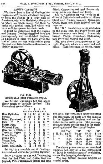
Even though it has been many years since I have ridden the rails at Griffith Park I still have a love for live steamers. Just seeing a steam train on TV is enough to stir up happy memories. Building one of these amazing machines would be an incredible adventure in model engineering. To be able to recreate the sights and sounds of the rail yard once again would be magical. For now I will just have to wait till I possibly retire to take on a several year project like a live steam train. I simply dont have the time, tooling or money to undertake such a complicated build. I do however have the means to build a stationary steam engine which will help hone my machining skills for the day I do take on a scale locomotive project. I have collected several small stationary steam engines over the years to help satisfy my need for steam. All of these engines were factory made and produced very little power if any. To build an engine of my own would be a very rewarding project not to mention a good lesson in machining. This is why I have decided to build a kit from rough castings which is the same way you would normally build a scale locomotive kit. The engine I am going to build is a 6CI horizontal steam engine which is a full scale 1/4 HP steam engine replica of a 1895 mail order catalog engine. The mill style steam engine was originally sold as a casting kit to amateur machinists of the day. You can see the actual page (below) from the 1895 Chas. A. Strelinger & Co. catalog that shows the horizontal high pressure engine (fig 1264). The casting kit would of cost $5.00 in 1895 which is equal to about $130 in our day (actually a pretty good price). Although it would have cost about a weeks wages to buy the kit :0P
I found the 6CI kit while looking for steam engine casting kits on eBay. The sellers of this kit suggested that it be built on a lathe no smaller than a 9 x 20 Southbend lathe. This had me concerned as I only have a 7 x 12 import lathe that is just about too small for the job. Casting all doubt aside I purchased the kit anyway and hoped for the best.
I received the 35 pounds kit in the mail from a company in Ohio. The factory packing was top notch for a heavy box of metal.
I unwrapped all of the cast pieces and set them out for a quick inventory of parts. I used the parts legend on the prints to verify the quantity and type of parts in the kit. This thing is pretty big!!!
Even though I have never built a kit like this before I could tell that these castings were very clean. The castings showed no signs of surface inclusions or leftover casting sand. Top notch parts!!!
The kit includes all of the engines hardware, Teflon gland seal packing, Teflon rings and even gasket material. All in all a pretty complete kit (less the 1/8 square steel key stock needed for the flywheel).
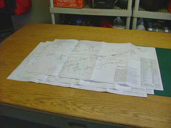
I spent some time and studied the prints for a few hours to get familiar with the parts I will need to machine. From the looks of it I will be learning a lot about machining methods with this one :0)
Now just so I get this off my chest in the beginning I want to remind my readers that I will be attempting to build this large kit on very small equipment. The undersized lathe & mill I will be using will force me to get creative with my machining methods to even get this project to work. This means that I cannot recommend that someone go out and buy the same lathe in hopes of building a successful kit. My main goal in posting this build is to help demonstrate to the novice how to navigate around machine tools and for the most part share my experience with the kit. I am by no means an expert machinist so this will be a learning experience for me as well as my readers. There may very well be more productive methods of machining than the ones I use during this build which is understandable considering I have limited experience with machining :oP The actual tools I will be using for the build will include my Harbor Freight 7 x 10 metal lathe, my Harbor Freight micro mill and various attachments. You can see my 7 x 10 lathe below which has served me well for over 100 hours of machining.
The Harbor Freight 47158 micro mill (seen below) has since been discontinued but still serves me well in the shop.
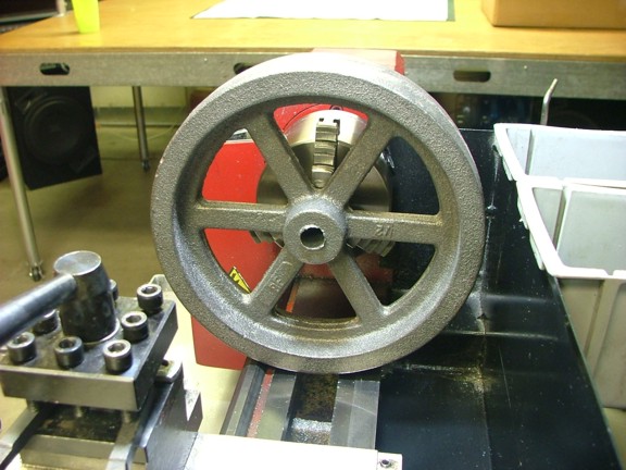
Now that I was ready to get started I decided to tackle parts that posed the most challenge to the equipment I am using. One of these parts was the flywheel. At almost 7 in diameter the flywheel will barely fit on the 7 x 10 lathe.
After some measuring I noticed that the casting seam of the flywheel was just a bit too much to swing over the bed of the lathe. This required immediate action so I used my grinder to level the seam to make clearance for the wheel.
As you can see below there is just barely enough room to swing the wheel over the bed! This is probably why the experts suggest a 9 swing lathe as a minimum for this kit.
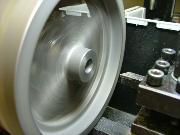
Now that I was ready to start the first machining function of the build I encountered a important lesson. This lesson is about setting up the casting properly in lathe to machine off only what the designer of the kit is wanting you to. In other words the casting has been designed a bit larger in areas to allow for the removal of metal in only those areas. For example the outer part of the flywheel is 1/4 larger than what the prints show as to allow for the lathe to remove the uneven cast surface and true up the wheel. It is important to find the designed center or axis of a spinning casting so that the majority of the casting that will not be machined away is spinning truly. In other words the inside of the wheel may wobble on a finished wheel if not properly set up before turning on the lathe. I spent some time adjusting the wheel in the three jaw chuck of the lathe to true up the hub of the flywheel to prevent wobbling. Once this centering adjustment was set I was committed to this center and all of the following machining steps will be built off of this axis. This is important or the wheel could wobble on the shaft due to poor centering. I plan on machining the axle hole first on the first chucking so that I can later use the actual crankshaft to turn the outside of the wheel to ensure the flywheel spins perfectly true (more on that later).
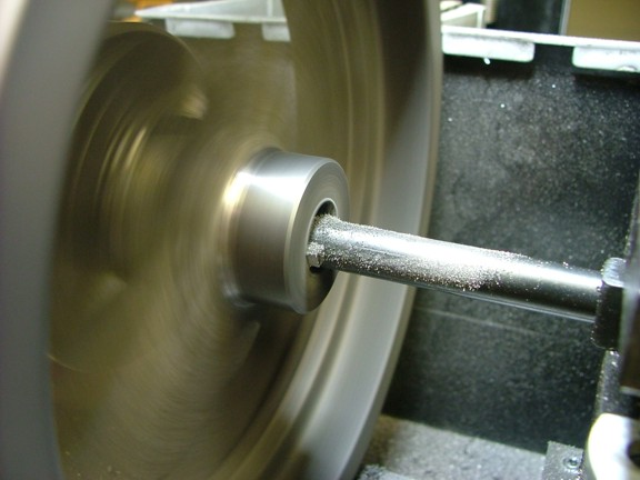
To start off the build I decided to face the outside of the hub and get a feel for the cast iron alloy. Unlike most of the steels I have machined before the cast seems to crumble off into more of a powder instead of chip up like carbon steel.
To clean up the outside of the hub I decided to use a custom 1/4 round carbide cutter that I made on the bench grinder (more on this later). This 1/4 round edge finishes up nicely to the rounded casting of the spokes.
Now the next step was to bore a axial hole in the middle of the hub. For this I used a 3/8 boring bar with a 1/8 High Speed Steel or HSS cutting bit. I used the mechanical feed of the carriage to drive the cutter in progressive cuts down the middle of the hub.
My goal was to make the hole exactly at .624 which was slightly larger than the steel shaft to be used for the crankshaft. Once I got close to the measurement I made very small cuts to not overshoot the size and ruin the casting. Of course this takes patience and if you have none I suggest you forget building a casting kit :oP
After several successive passes the bore was at .624 at which the steel crankshaft stock was able to fit. My first real machining operation was complete :0)
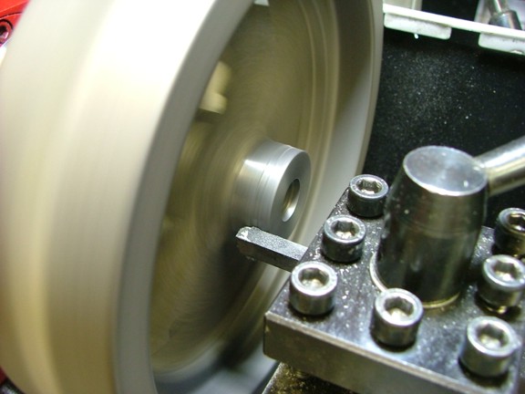
My next task was to cut a 1/8 keyway in the hub of the flywheel to help keep it from spinning on the crank shaft of the engine. Traditionally a keyway is cut in a hub with what is called a broaching tool. This tool has a cutter with progressively arranged teeth that when pressed through the hole will cut a square slot in the bore of the hole. Of course I do not have the tool nor would I buy the $150 one-time-use tool for this build so I did what I do best, improvise!!!. To broach the keyway in the hub I decided to use the boring bar to progressively score the hole until I get the desired square hole in the bore as needed. Before I could do this I needed to secure the flywheel with a c clamp as to not allow the lathe chuck to move during the scoring process.
Now that the flywheel cannot move I could set up the boring bar to the desired location for the cut. You will notice below that the HSS bit has been positioned with the cutting edge facing the hub.
Using the carriage hand wheel I cranked the carriage into the hub while adjusting the cutter to make the first passes. I then repeated the cut until I felt no resistance from the boring bar. I then advanced the boring bar out of center in .002 increments and repeated the broaching process.
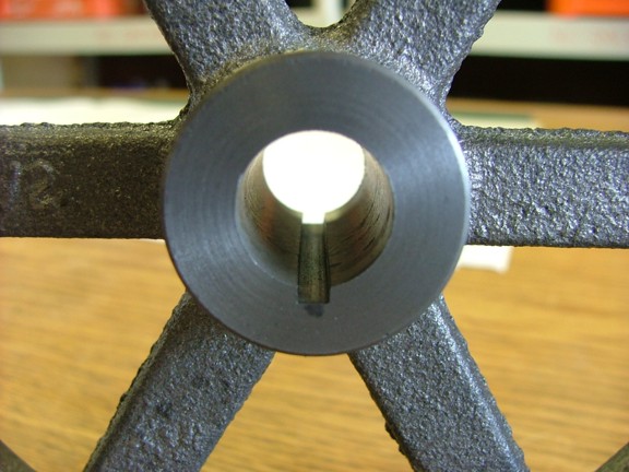
Amazingly enough the process worked very well leaving a clean square hole in the flywheel ready for the 1/8 key stock :0)
The next step will be to build the half shaft that will be used as an arbor to finish the rest of the flywheel. Please join me again for the next episode of the build very soon. Until then be safe my friends!!!